


TF Beechcraft Bonanza F33A Build

 07-02-2019, 11:14 AM
#52

Thread Starter
Part II - Hinging the Elevators to the Stabilizer
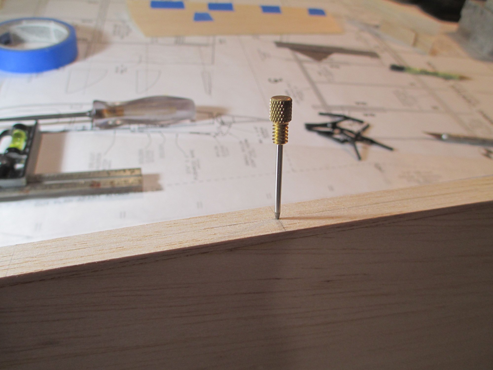
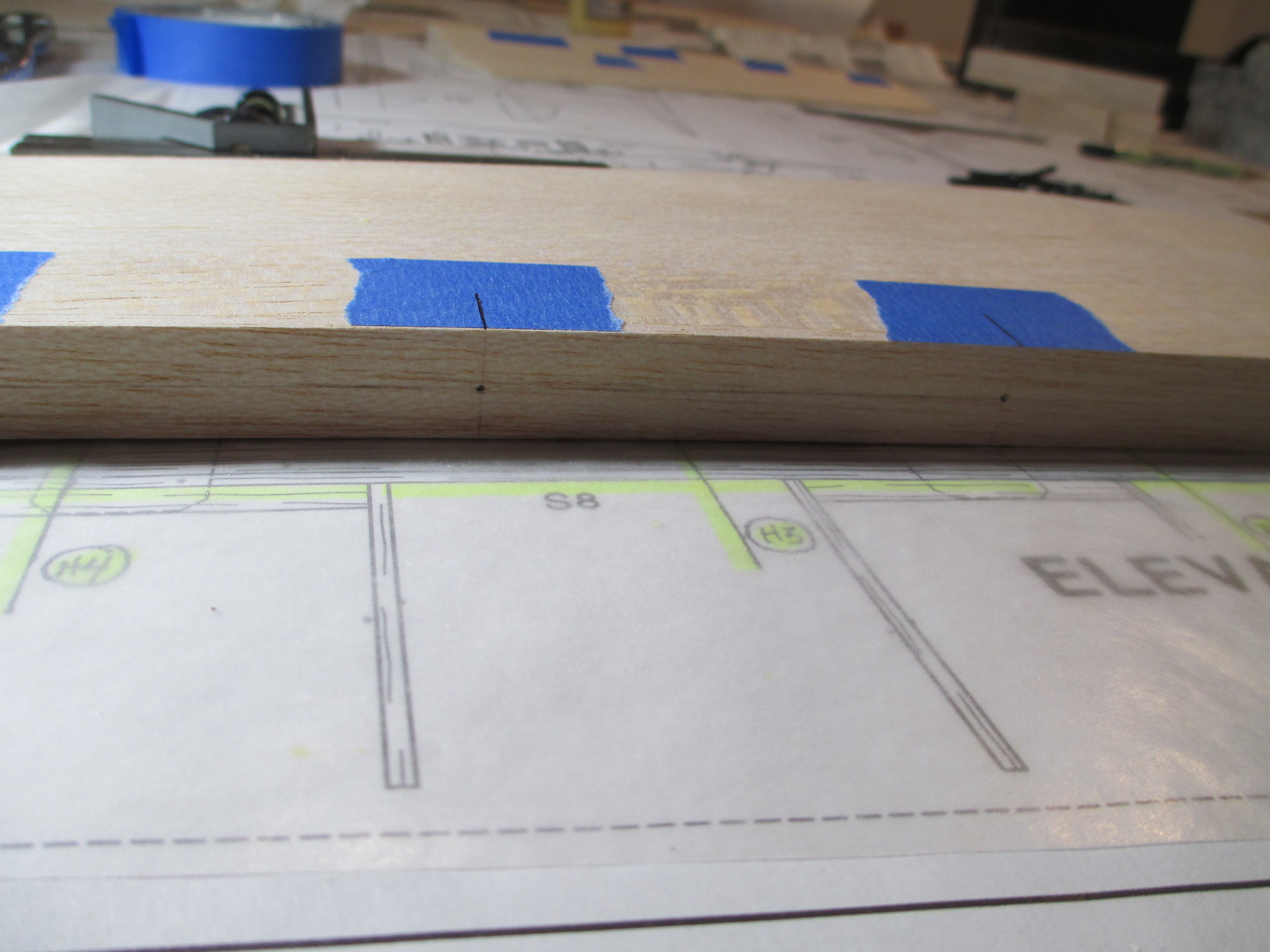
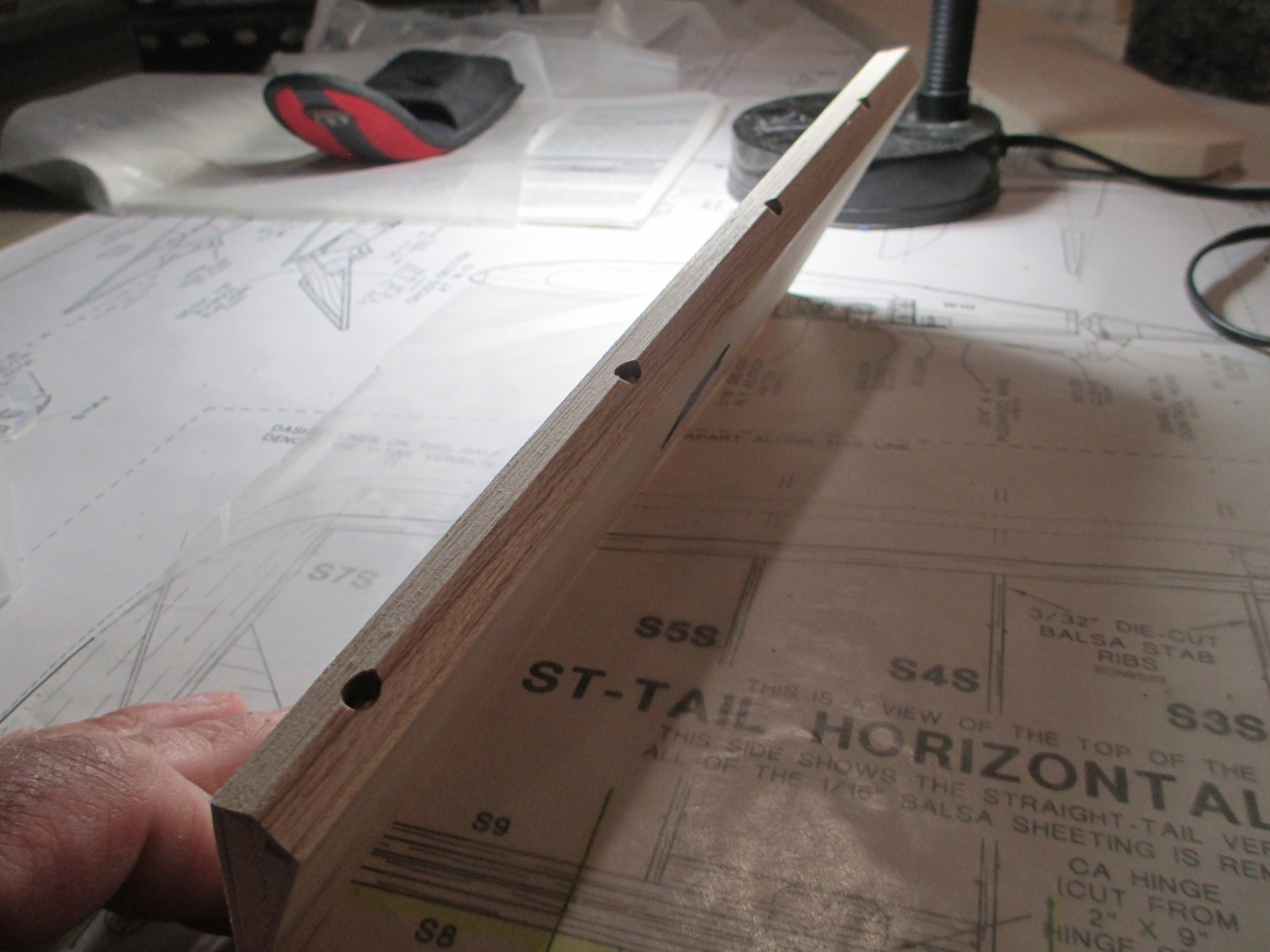
With all the hinge point locations marked on the stab's TE, I use the scribe tool that is screwed into your square and make an indentation in the center of the pencil marks. If you don't have or lost the scribe tool an awl works just as well.
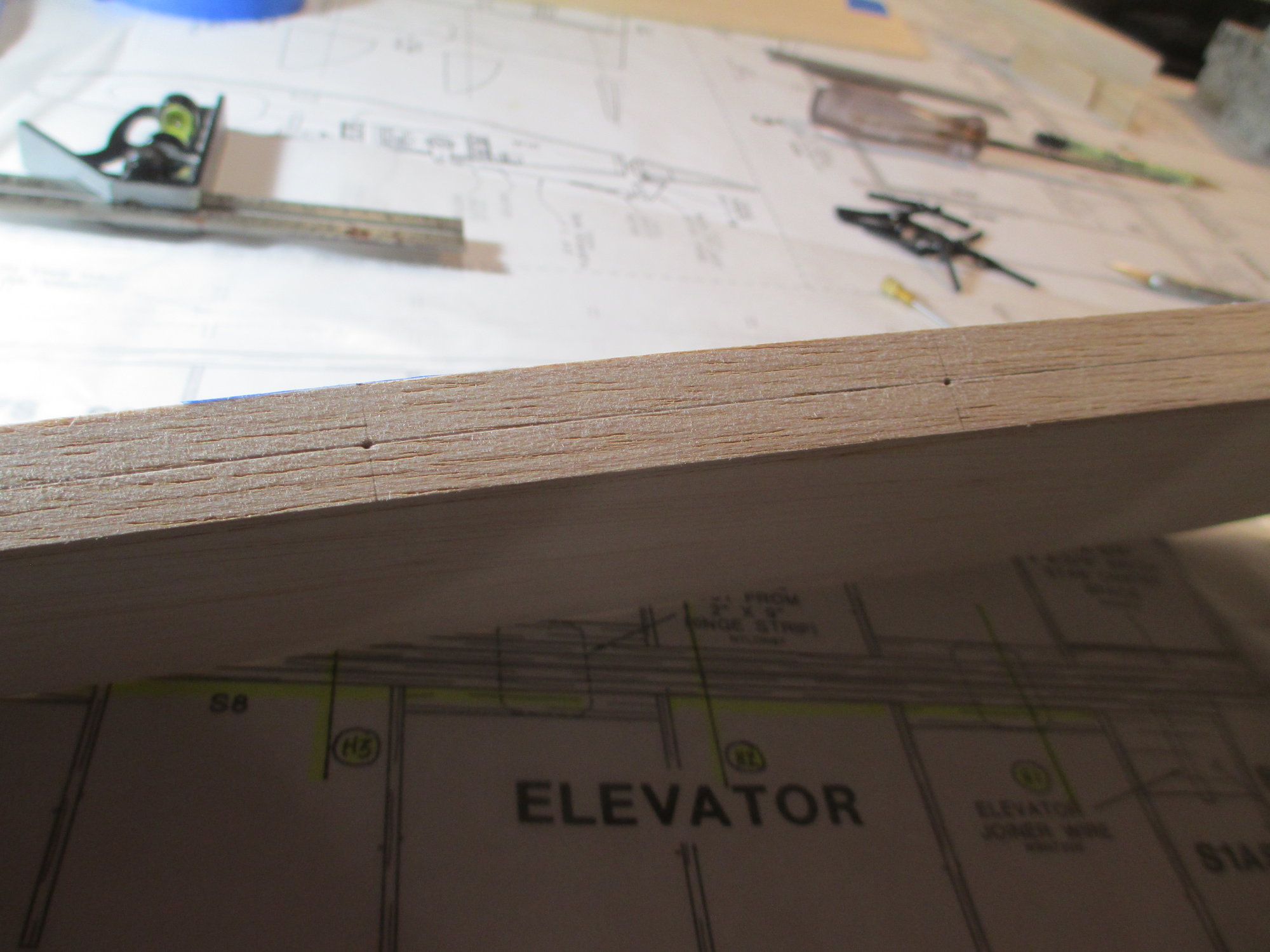
This is what it should look like.
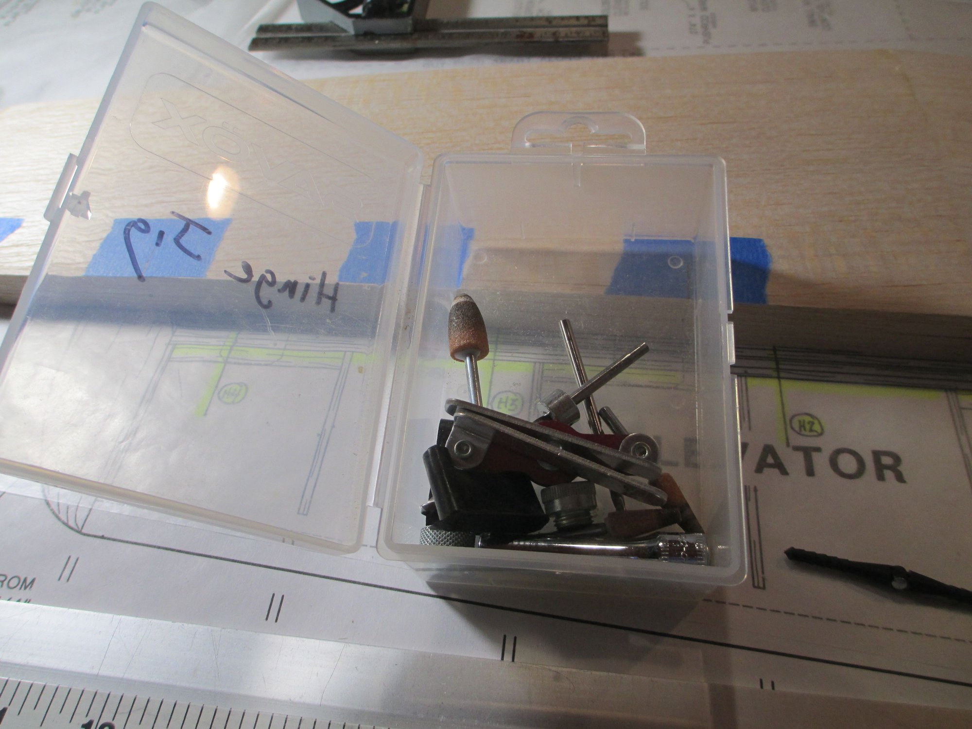
I find it convenient to have all of the tools that I need to install hinge points in one storage box. I'm using an old servo box for this purpose.
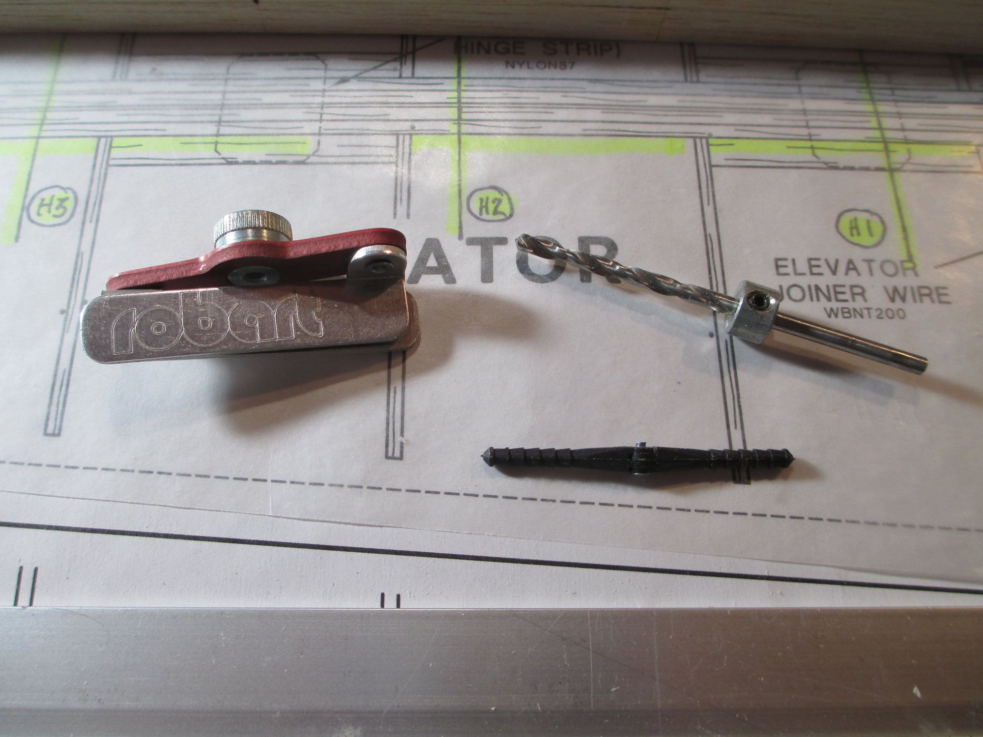
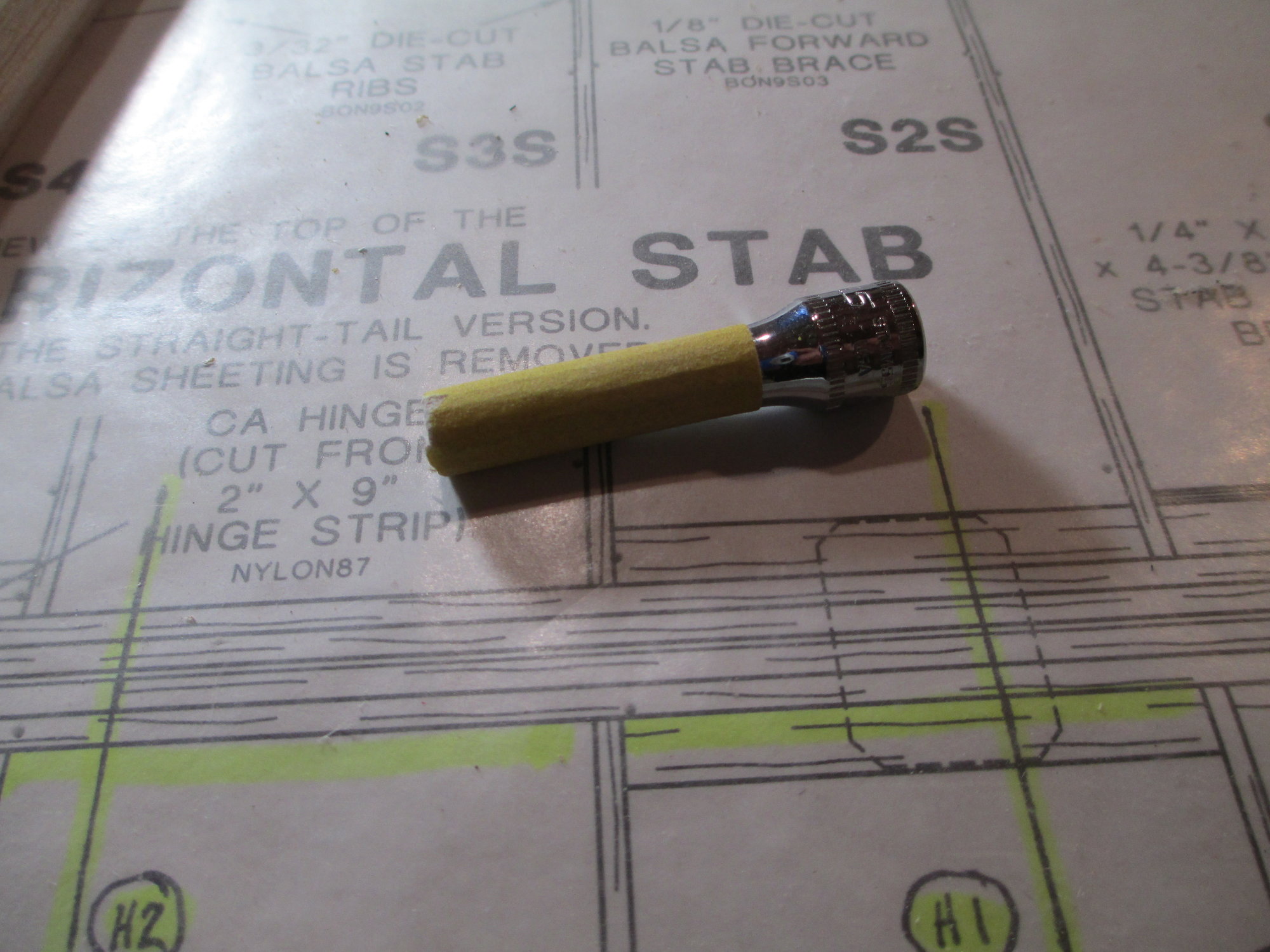
This is a jig that Robart sells, if you want to install your hinge points straight and true it's really a must have. The threaded top knob is removable insert that will accommodate the different size hinge points that Robart offers which are 3/32,1/8 and 3/16. I've installed the 1/8" hinge points insert for my application. Be sure to use a new or sharp 1/8" drill bit, which I've equipped with a depth stop that you can find at your local hardware store.
Place the jig over the TE of the stab, insert an awl to locate the indentation previously made ensuring the hole is drilled at the correct location. You could also just look through the top hole and just site the indentation if you prefer. Stay tuned for Part III...
With all the hinge point locations marked on the stab's TE, I use the scribe tool that is screwed into your square and make an indentation in the center of the pencil marks. If you don't have or lost the scribe tool an awl works just as well.
This is what it should look like.
I find it convenient to have all of the tools that I need to install hinge points in one storage box. I'm using an old servo box for this purpose.
This is a jig that Robart sells, if you want to install your hinge points straight and true it's really a must have. The threaded top knob is removable insert that will accommodate the different size hinge points that Robart offers which are 3/32,1/8 and 3/16. I've installed the 1/8" hinge points insert for my application. Be sure to use a new or sharp 1/8" drill bit, which I've equipped with a depth stop that you can find at your local hardware store.
Place the jig over the TE of the stab, insert an awl to locate the indentation previously made ensuring the hole is drilled at the correct location. You could also just look through the top hole and just site the indentation if you prefer. Stay tuned for Part III...
Last edited by VincentJ; 07-02-2019 at 11:39 PM.
07-02-2019, 11:15 AM
#53
Member

Mike, good luck doing any bench time with that little cute girl around! Vince, looking good per the norm. I was also wondering where all the blue tape went. You had it!  (I use a lot of it myself. Used it for clamping primarily before I saw those great clamps.)
(I use a lot of it myself. Used it for clamping primarily before I saw those great clamps.)

 07-03-2019, 12:21 AM
#55
Thread Starter
Part III - Hinging the Elevators to the Stabilizer
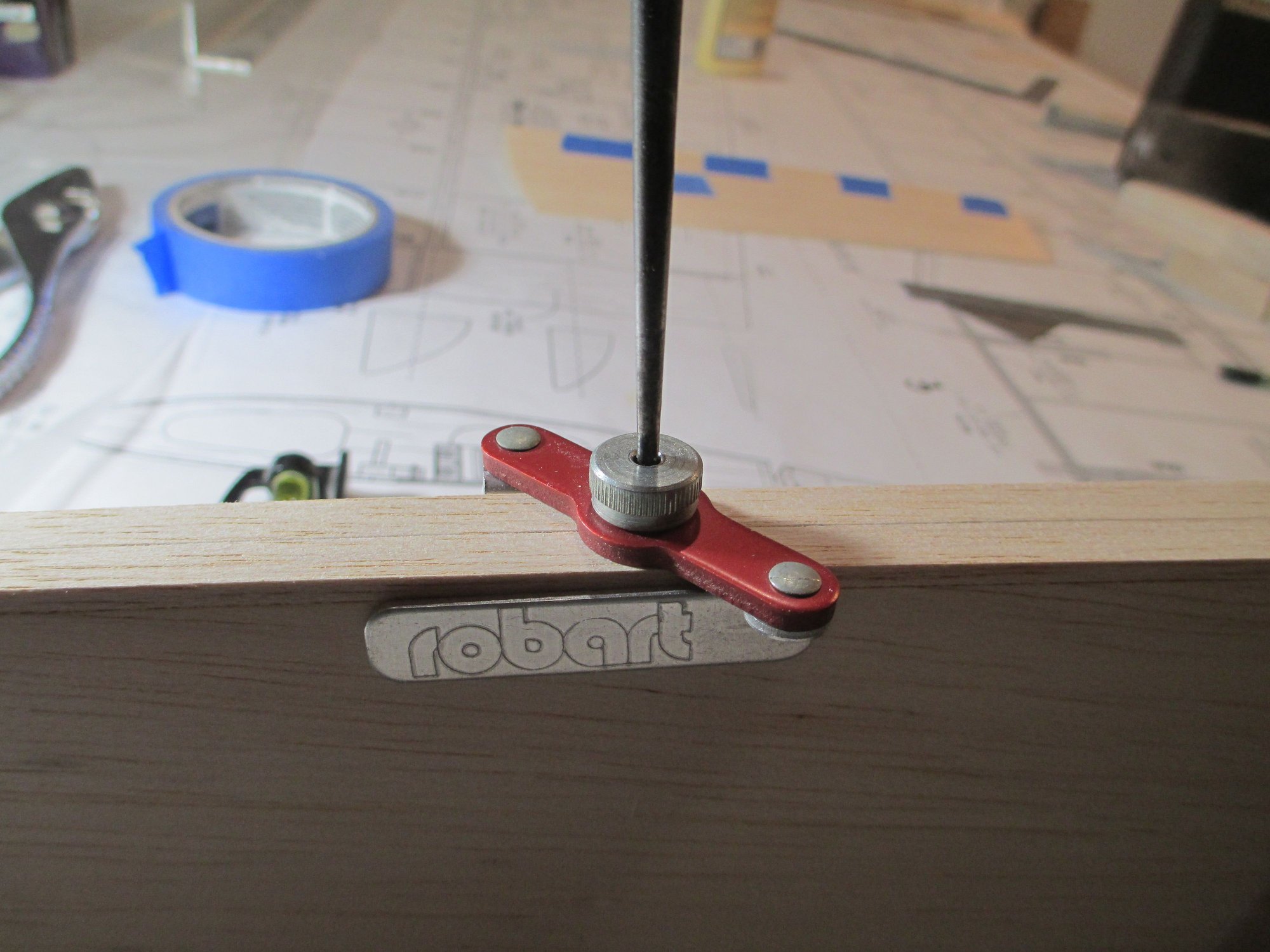
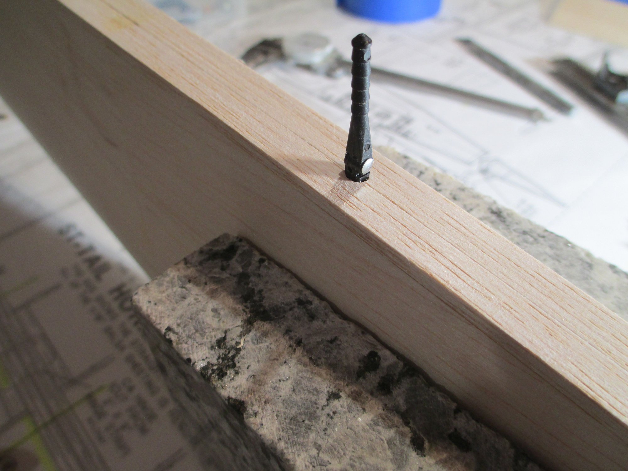
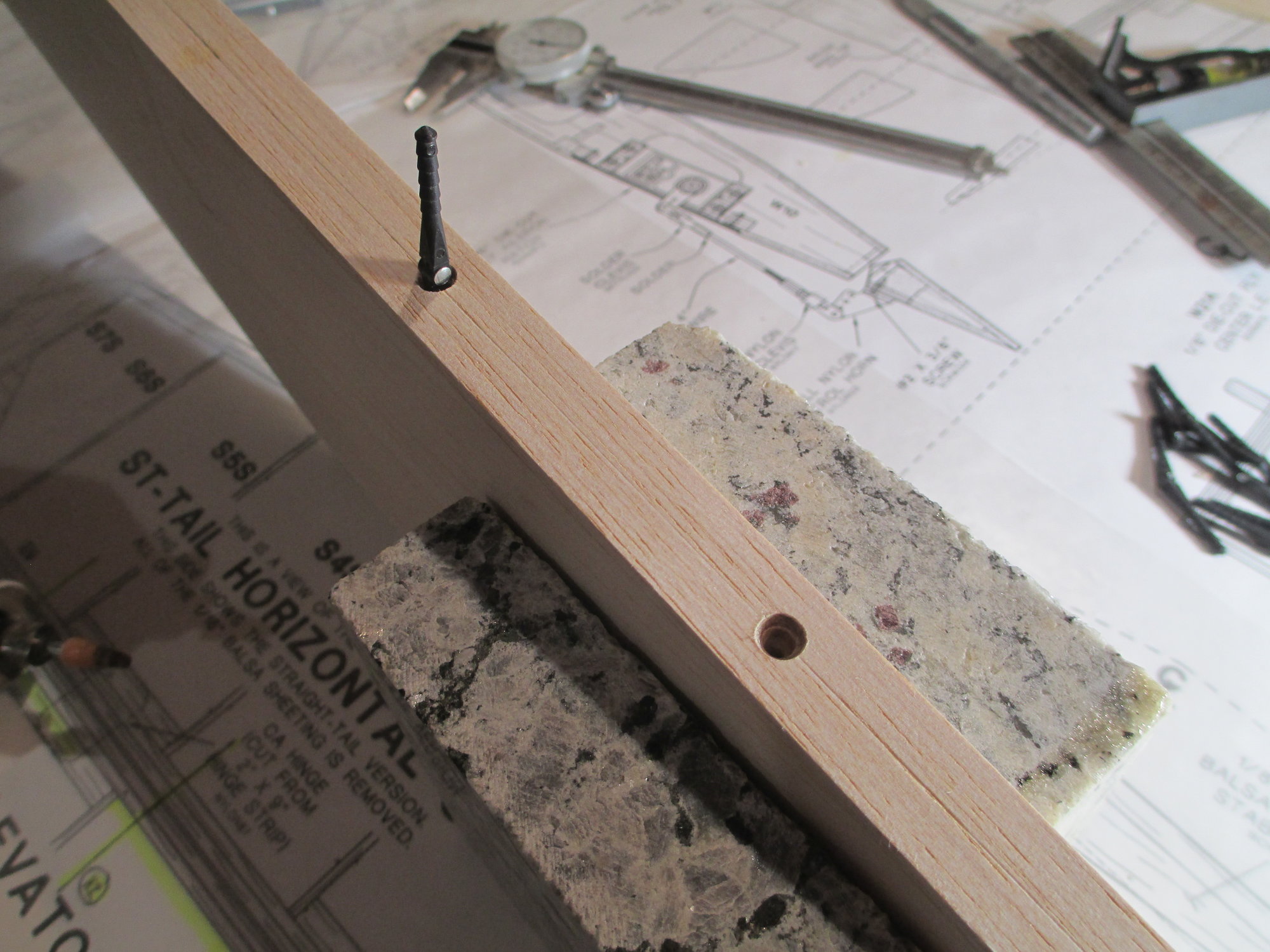
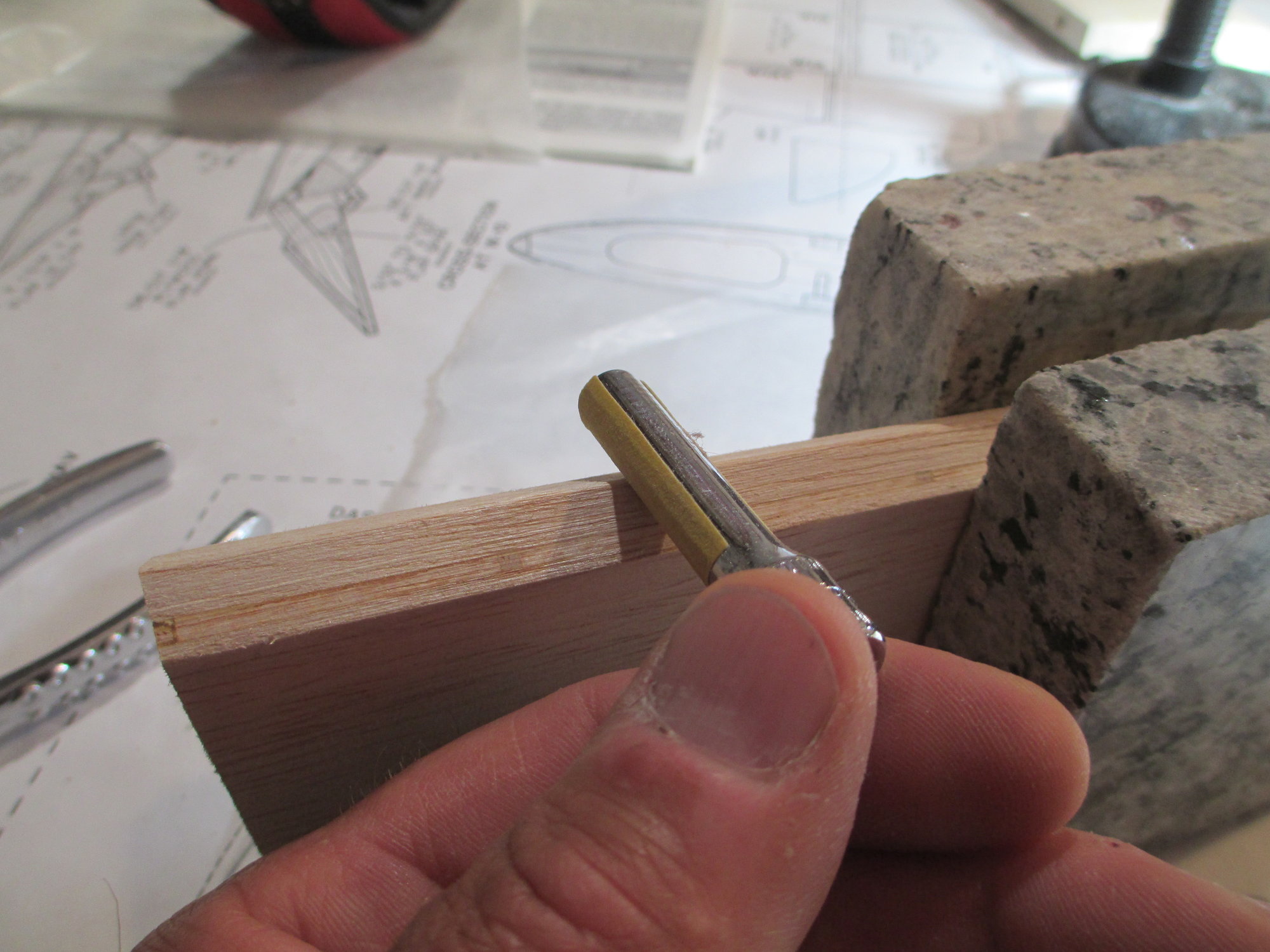
Remove the awl and insert your 1/8" drill bit chucked in a cordless drill. The jig will ensure the hole is straight and plumb.
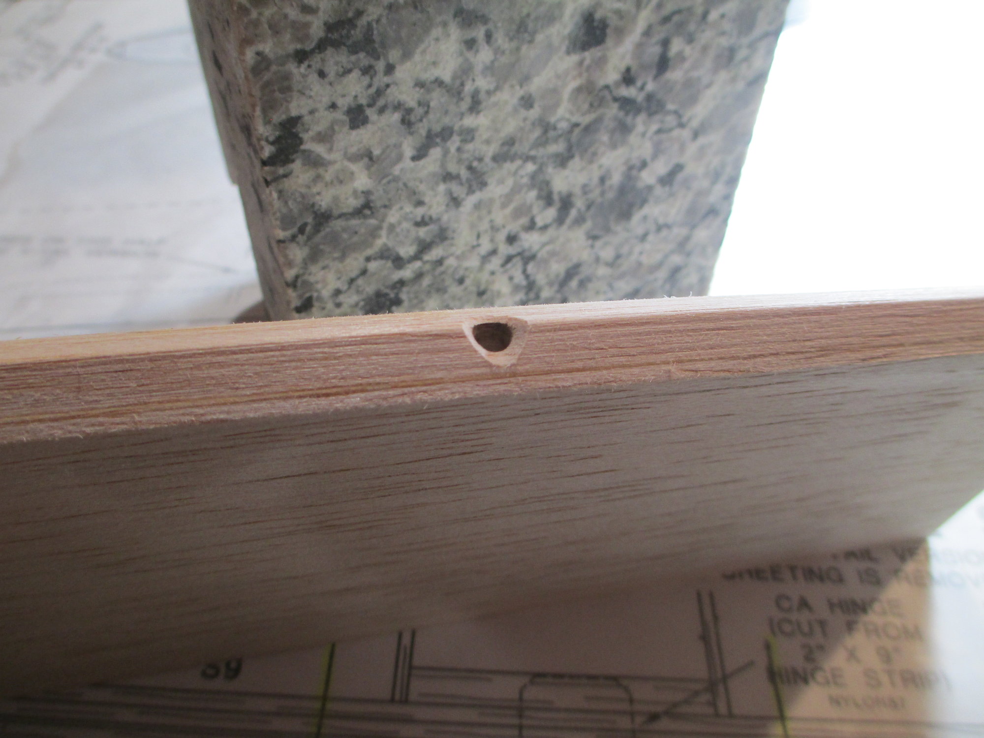
All of the 1/8" holes have been drilled, but you're not done yet!
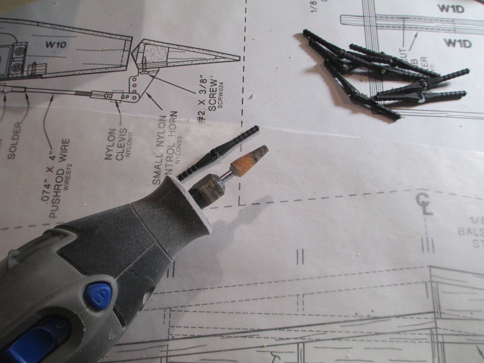
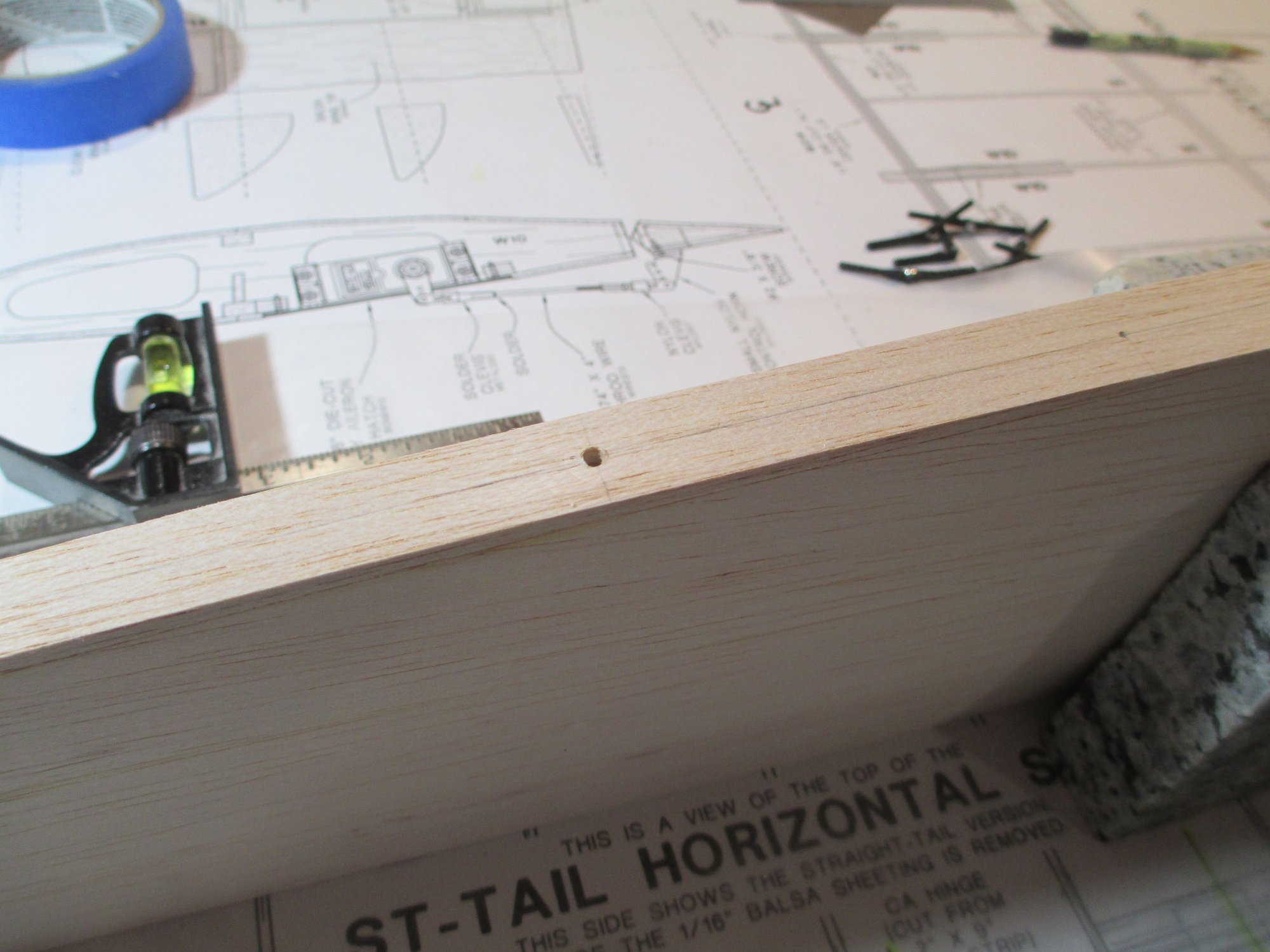
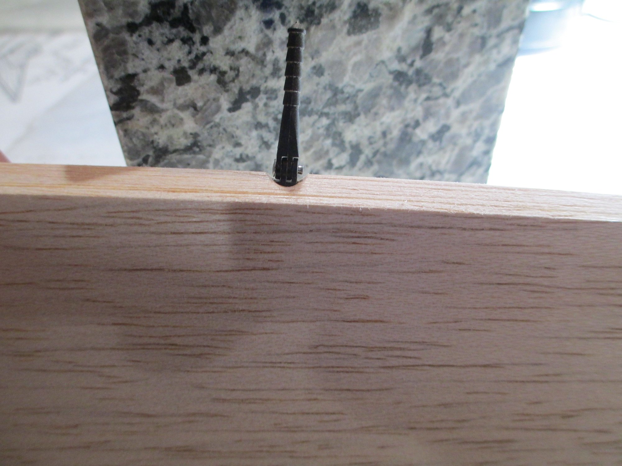
Look closely at the hinge point. Note that the barbed portion of the hinge point is straight, in other words, its diameter is the same from the first top barb to the bottom sixth barb. Above the top barb the hinge point starts to taper. We need to account for that for a proper fit. I use a tapered stone chucked in my Dremel tool.

This is done freehand and without the aid of the jig. Don't worry it's a piece of cake!
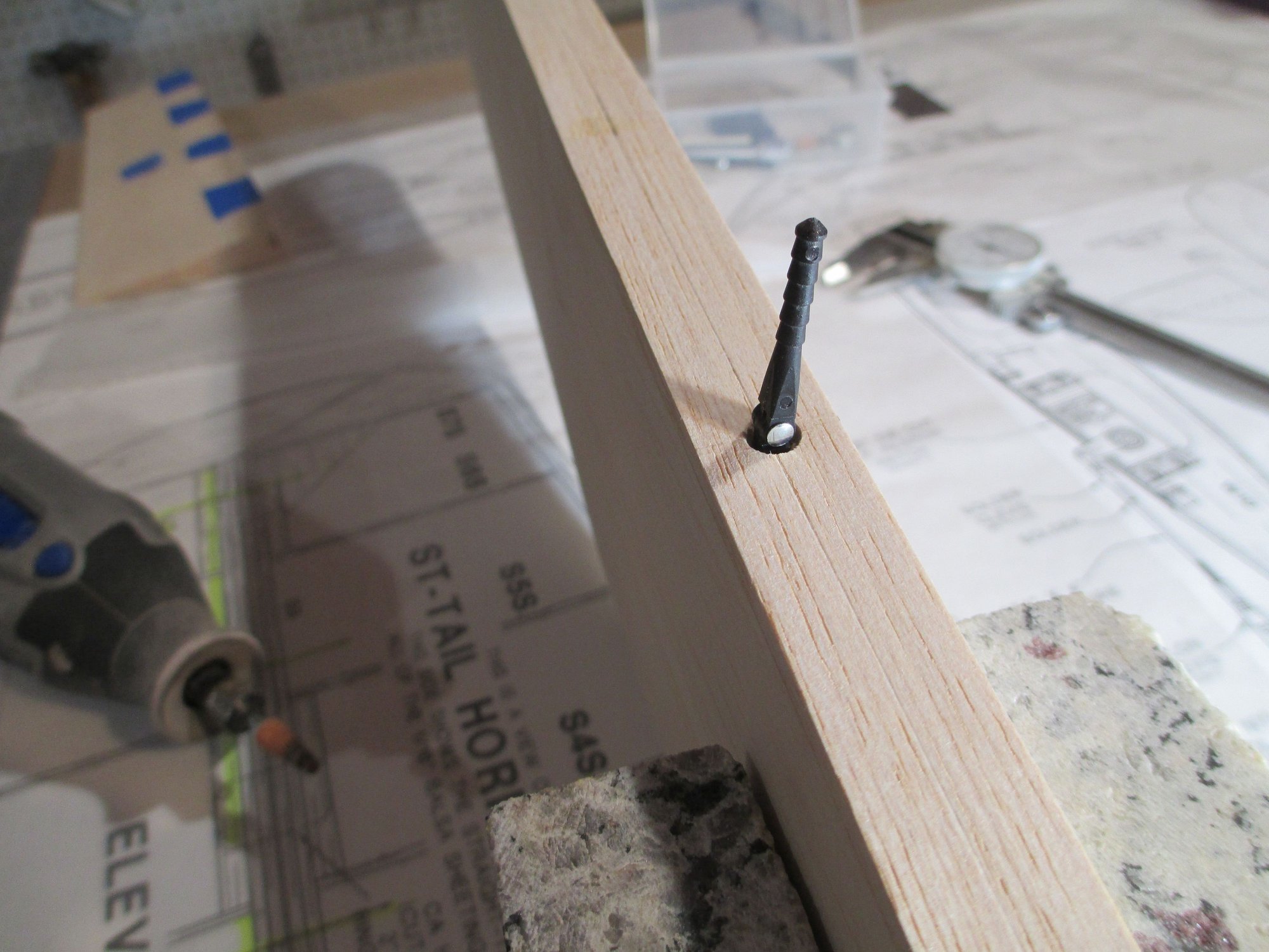
Inserting the hinge point, you'll notice that we now have to accommodate for the larger diameter of the hinge point knuckle...

So it's back to the Dremel tool with yet another stone bit to widen the top of the hinge point opening.
OK, now that's much better. Now you're done!

Remove the awl and insert your 1/8" drill bit chucked in a cordless drill. The jig will ensure the hole is straight and plumb.
All of the 1/8" holes have been drilled, but you're not done yet!
Look closely at the hinge point. Note that the barbed portion of the hinge point is straight, in other words, its diameter is the same from the first top barb to the bottom sixth barb. Above the top barb the hinge point starts to taper. We need to account for that for a proper fit. I use a tapered stone chucked in my Dremel tool.
This is done freehand and without the aid of the jig. Don't worry it's a piece of cake!
Inserting the hinge point, you'll notice that we now have to accommodate for the larger diameter of the hinge point knuckle...
So it's back to the Dremel tool with yet another stone bit to widen the top of the hinge point opening.
OK, now that's much better. Now you're done!
Last edited by VincentJ; 07-03-2019 at 02:36 AM.
07-03-2019, 04:19 AM
#56
Thread Starter
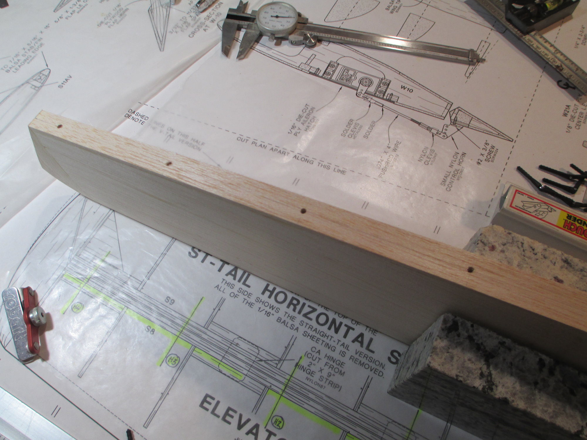
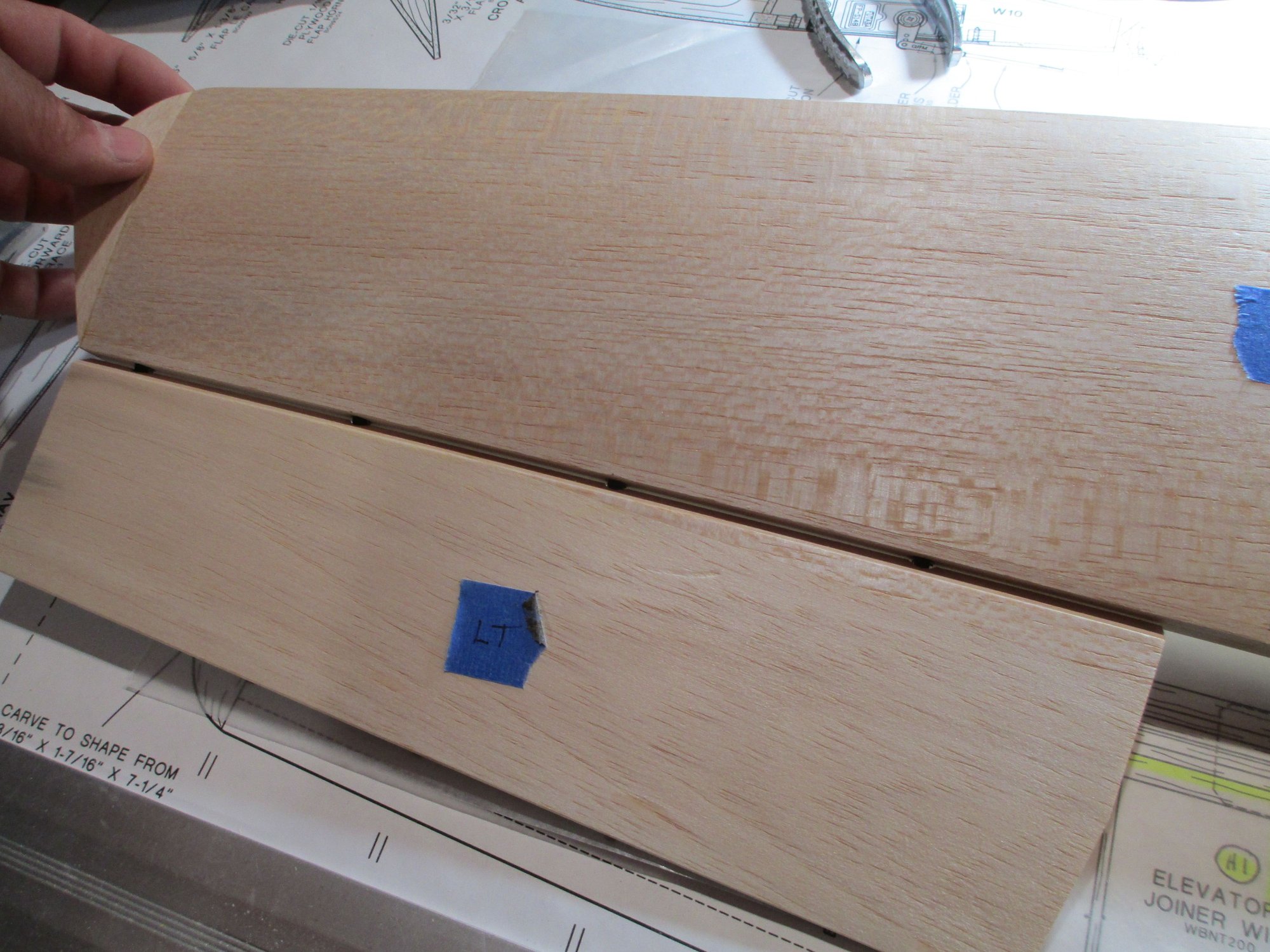
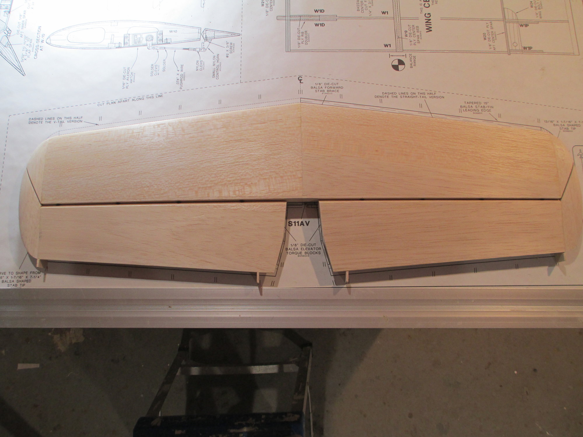
This morning I duplicated the same procedures on the elevator halves as I did on the stab.
My measurements were right on, both elevator and stab lines match. You may be wondering about the large hinge gap. This will be adjusted as soon as I bevel the elevators LE. More to follow...
07-03-2019, 11:21 AM
#59
Member
I saw your hinge tutorial on the Sig 4* build on the hinges. I happened to have that Robart hinge tool which does help but I like the additional steps you include that I never thought of. You seem to be meticulous with good procedures. I would always bevel the control surfaces first and then use the hinge tool. I think that's how the kit instructions would always tell us. Having flat edges to lay the tool down makes so much more sense and is easier to work with. From now on I am questioning manuals and planning my steps better.
The following users liked this post:
rcFLYBOY14 (05-21-2020)
07-03-2019, 05:12 PM
#60
Thread Starter
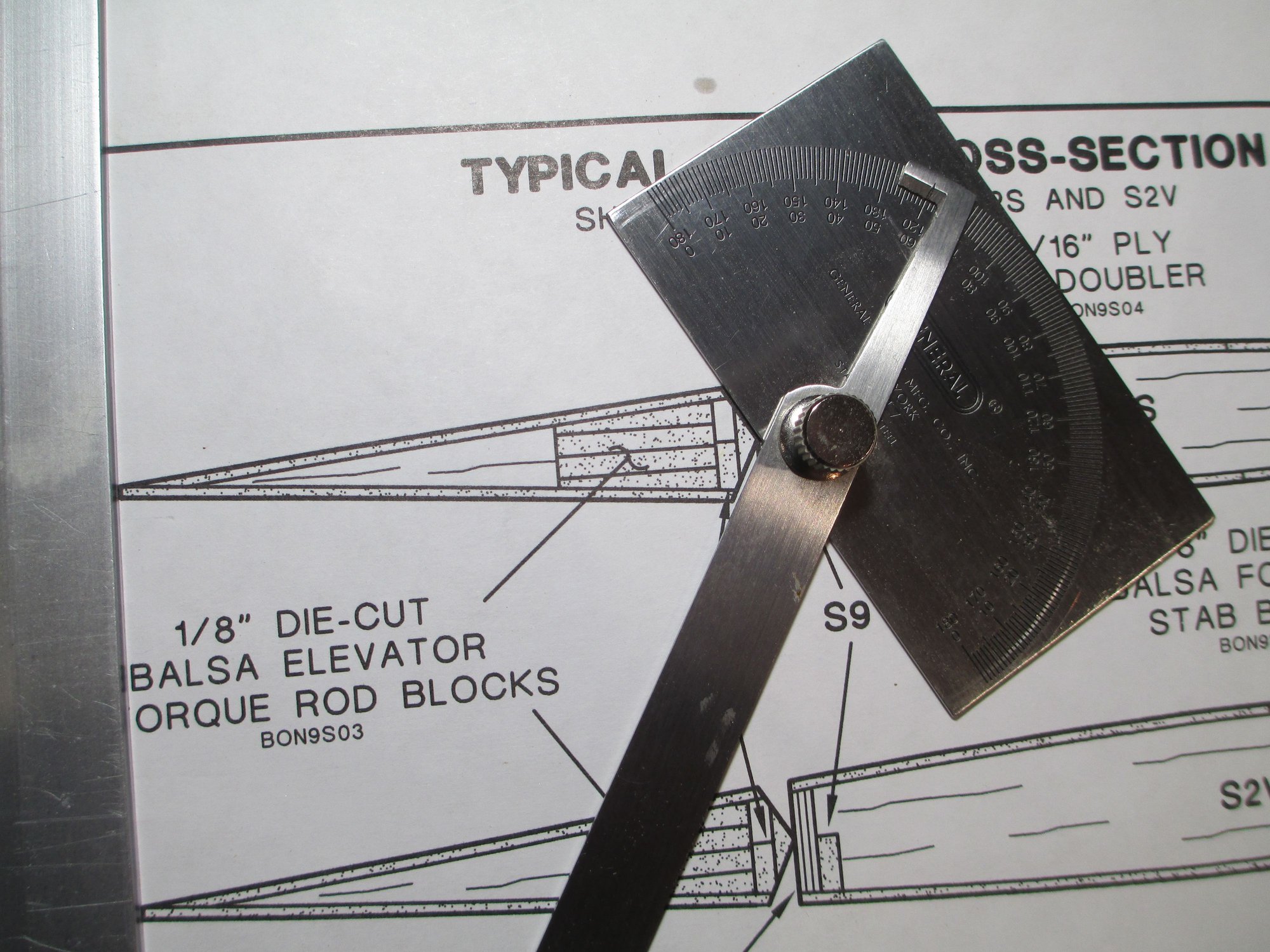
The LE bevel on each elevator is 60 degrees.

This is what I'll use to bevel those edges.
My home made bevel sander made quick work of it.
I like to keep things simple. I wrapped sandpaper around a deep socket.
I need to notch the top of each hinge opening to give clearance for the hinge knuckle.
A few passes and it's done.

This is what the hinge should look installed. The hinge line is flush with the tip of the bevel and the knuckle has room to flex.
Remember those large hinge gaps that I had before? Now the hinge gap is minimal.

Plenty of elevator deflection... I think it's good to go.
Last edited by VincentJ; 07-03-2019 at 05:15 PM.
07-03-2019, 08:25 PM
#61
My Feedback: (2)
HI Vincent, When you cover your tail section do you fill in the gap at the hinge line with covering folded in half to fit the gap on both sides of the stabilizer and the elevator. My old mentor did this many years ago and he never shared how to do it! Do you also cover the tail section first then leave enough of a gap so you can glue the stab to the fuse?
Thank You
Michael Johnston
Thank You
Michael Johnston
07-04-2019, 12:43 AM
#62
Thread Starter
Mike, my 3-D friends seal their hinge line gaps, but I never have. It's a pretty simple process to do. Some use the same plastic covering (Ultracote/ Monokote) ironed between the beveled sides of their control surfaces. Others use 3M Micropore or Blenderm tape. The Micropore is white vs the Blenderm being clear. You Tube I'm sure has tutorials showing the process...
When I built my Four Star, I covered all of the tail surfaces before gluing onto the fuselage much like an ARF. In this particular case I will be glassing the entire model and painting so I may glass the stab before I glue to wing, not sure yet...
When I built my Four Star, I covered all of the tail surfaces before gluing onto the fuselage much like an ARF. In this particular case I will be glassing the entire model and painting so I may glass the stab before I glue to wing, not sure yet...
Last edited by VincentJ; 07-04-2019 at 05:20 PM.
07-05-2019, 03:24 PM
#64
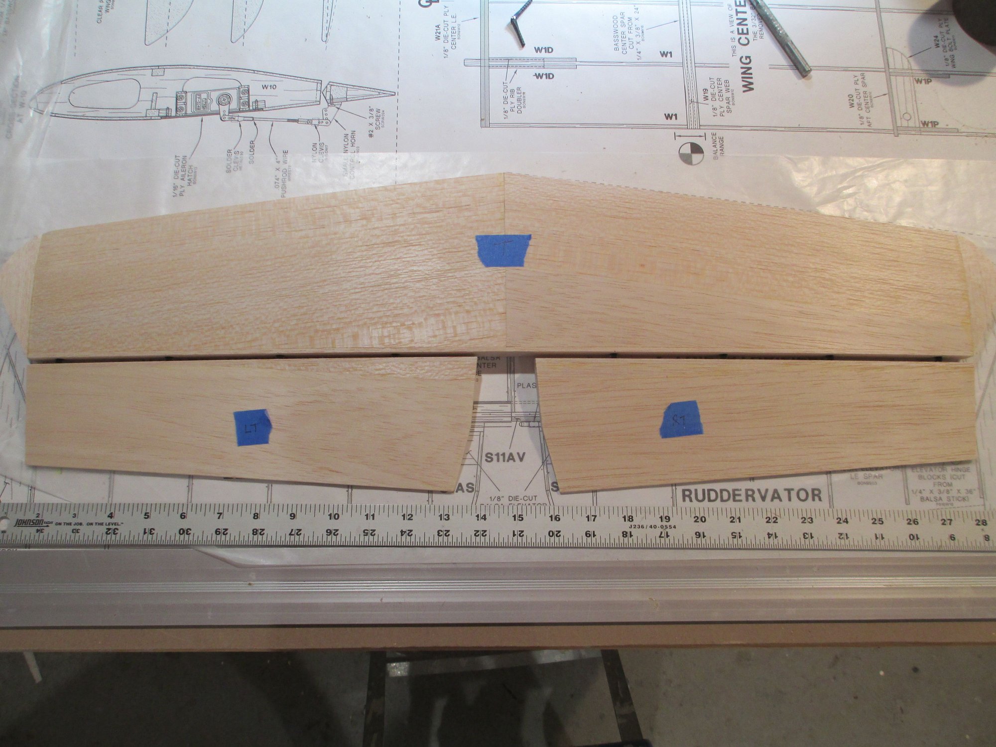
Thread Starter
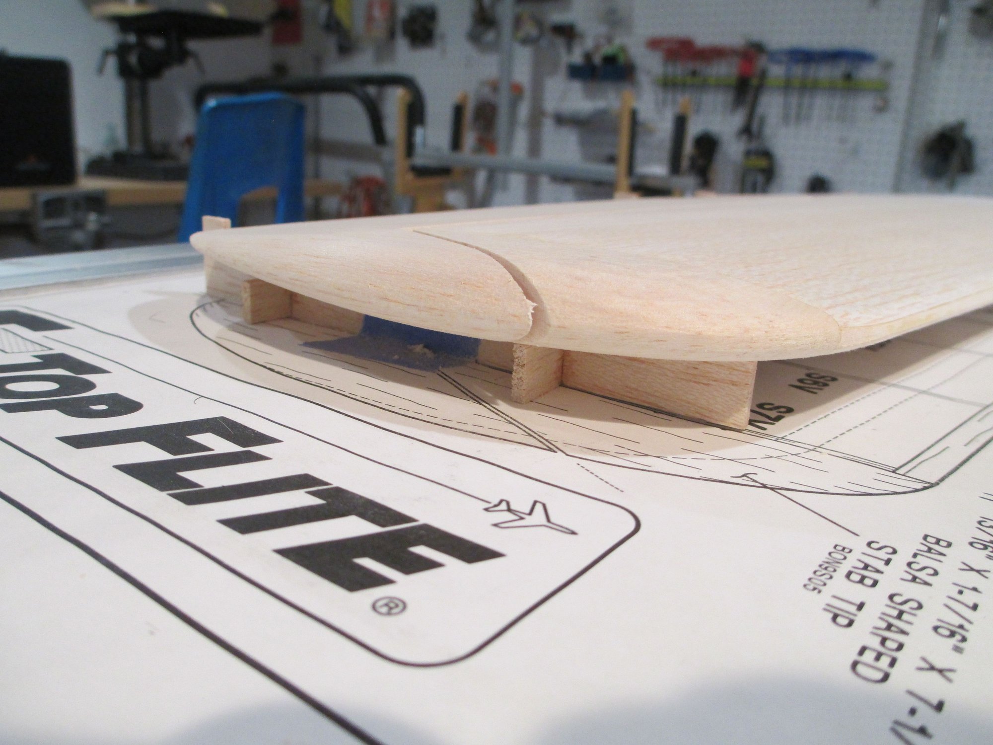
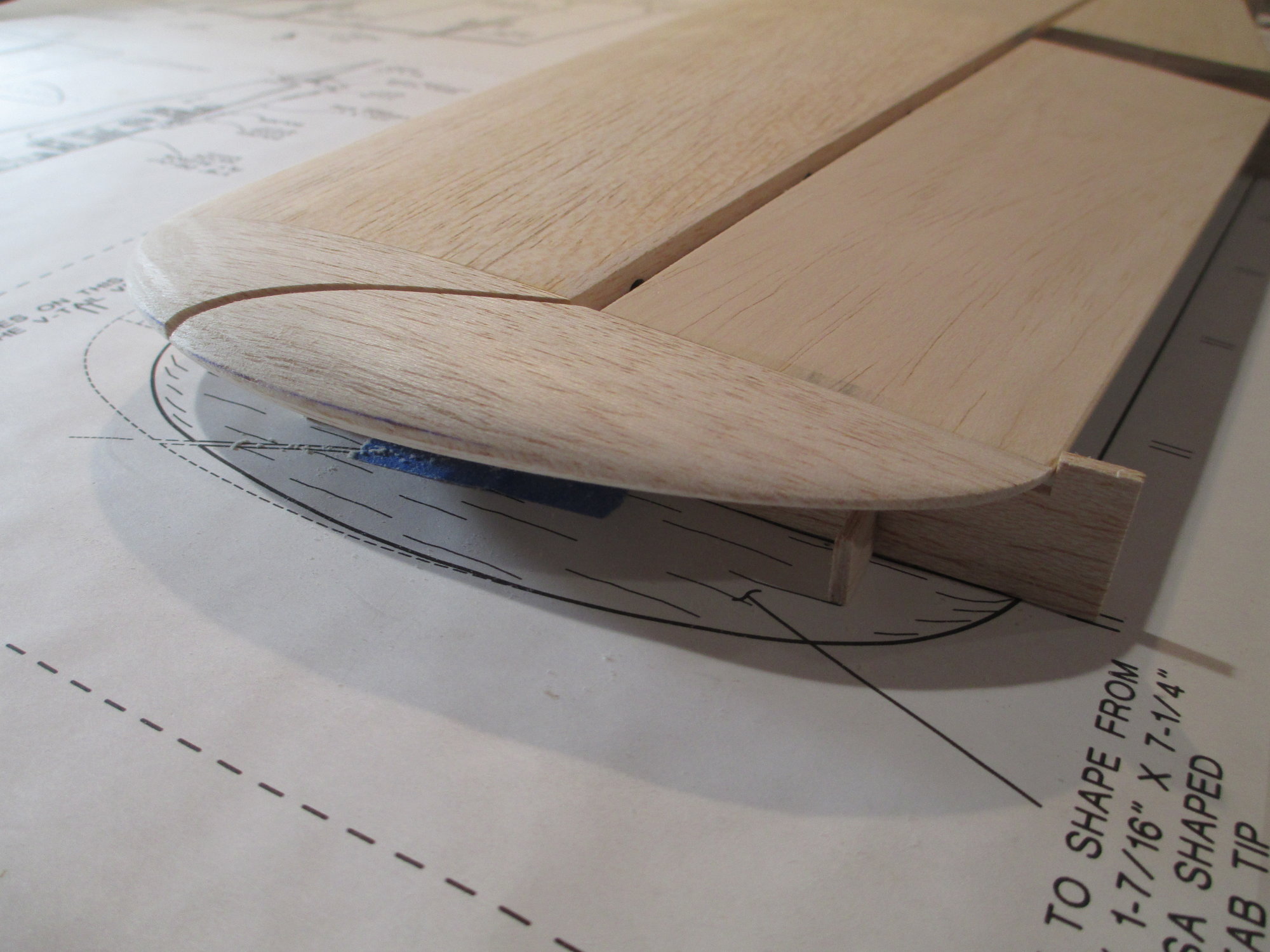
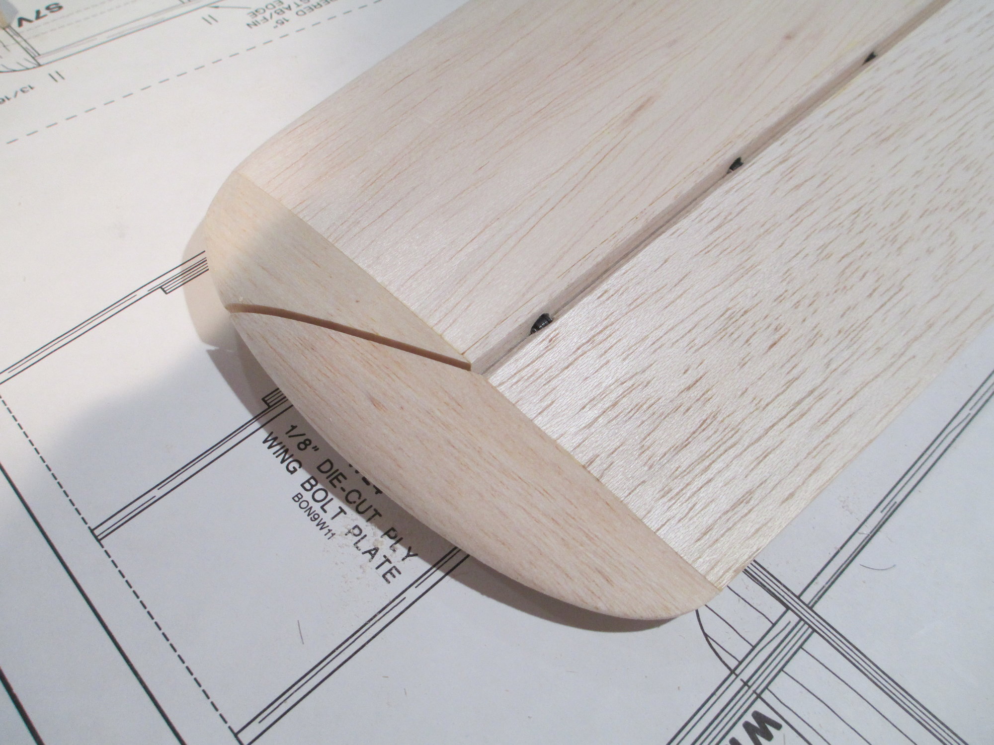
To shape the wing tips, the elevators first have to be set at their neutral position. After some head scratching I had an epiphany. I fished out of the garbage the bottom portions of the cradles that were once part of the ribs that accomplished that very task. I added some cross brackets so they could stand on their own.
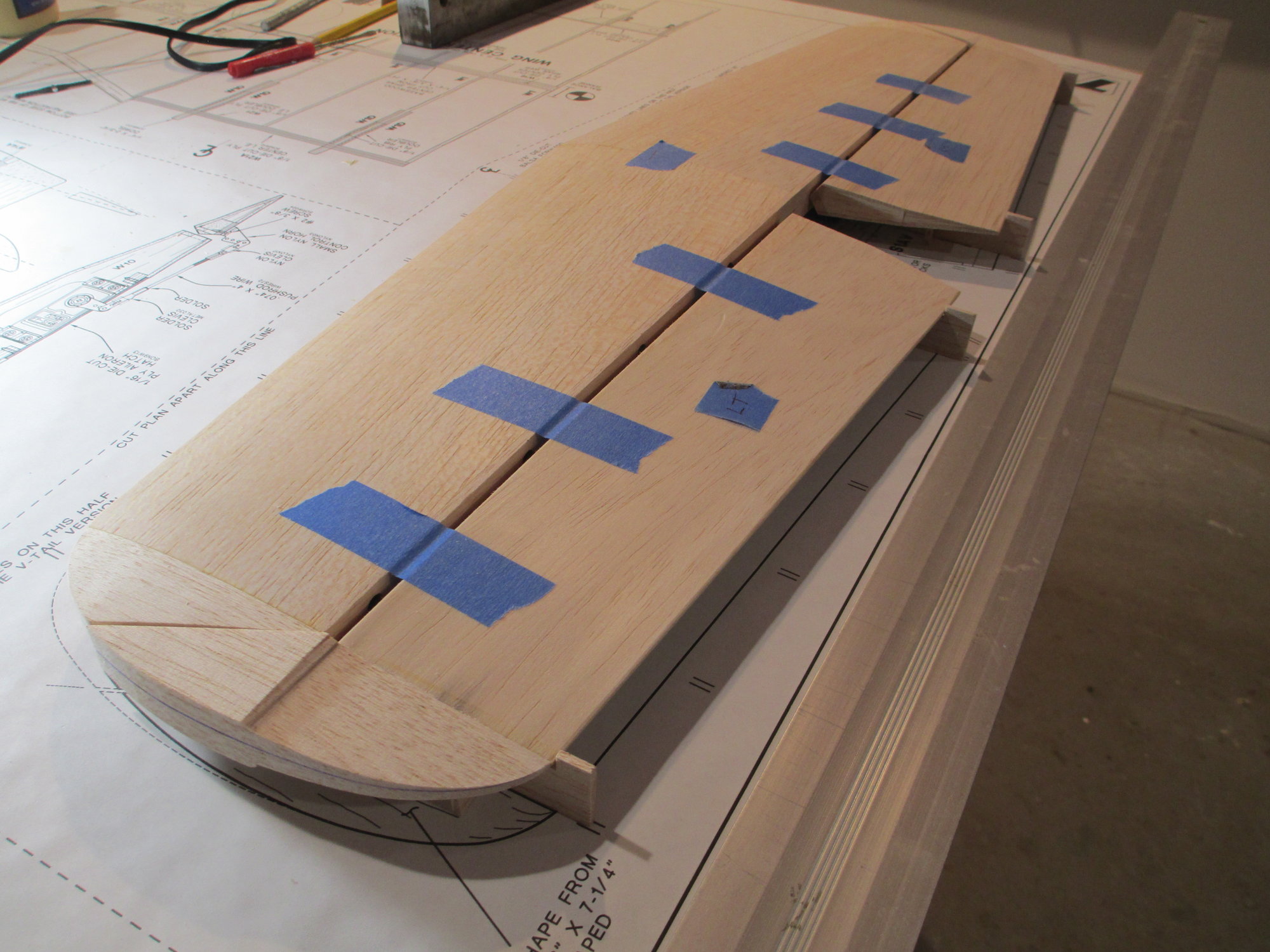
They worked like a charm. Now I can shape those tips!

Initial rough shape completed, now it's time to taper them.
Last edited by VincentJ; 07-05-2019 at 03:56 PM.

 07-06-2019, 09:16 AM
#66
Thread Starter
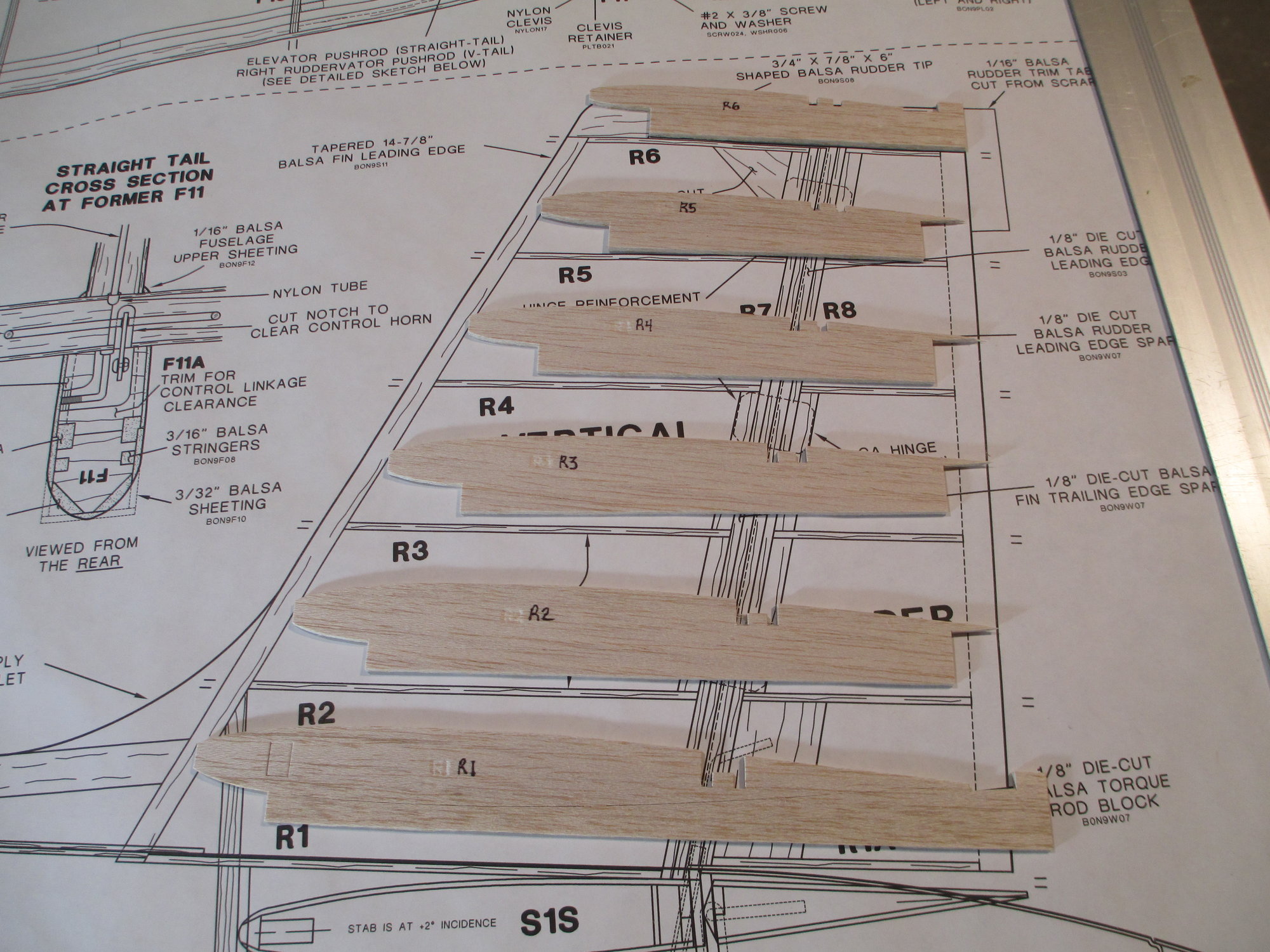
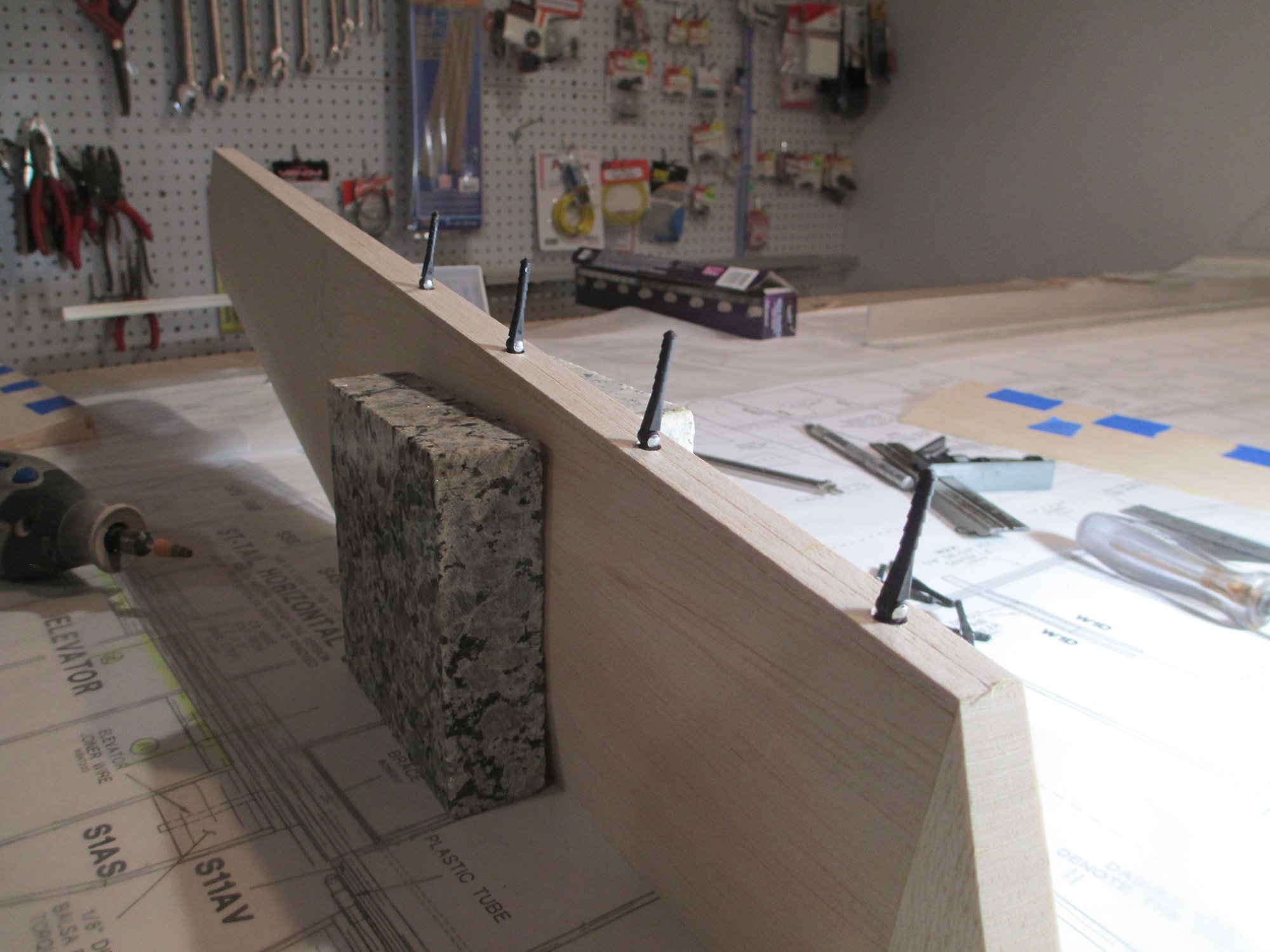
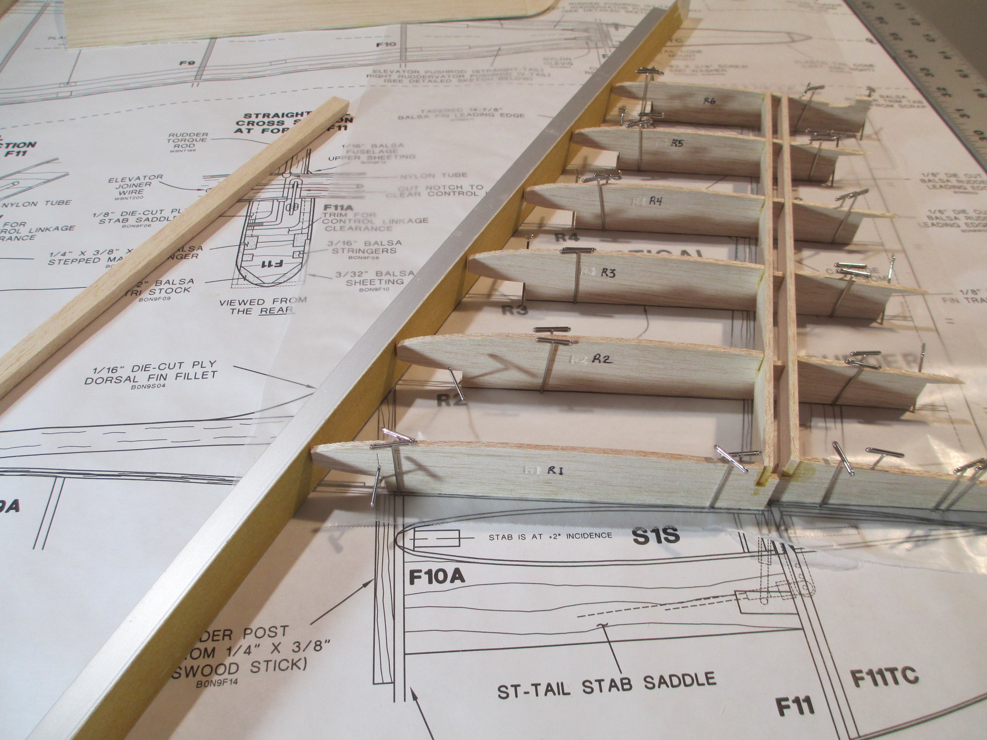
Construction on the Fin/Rudder has begun.
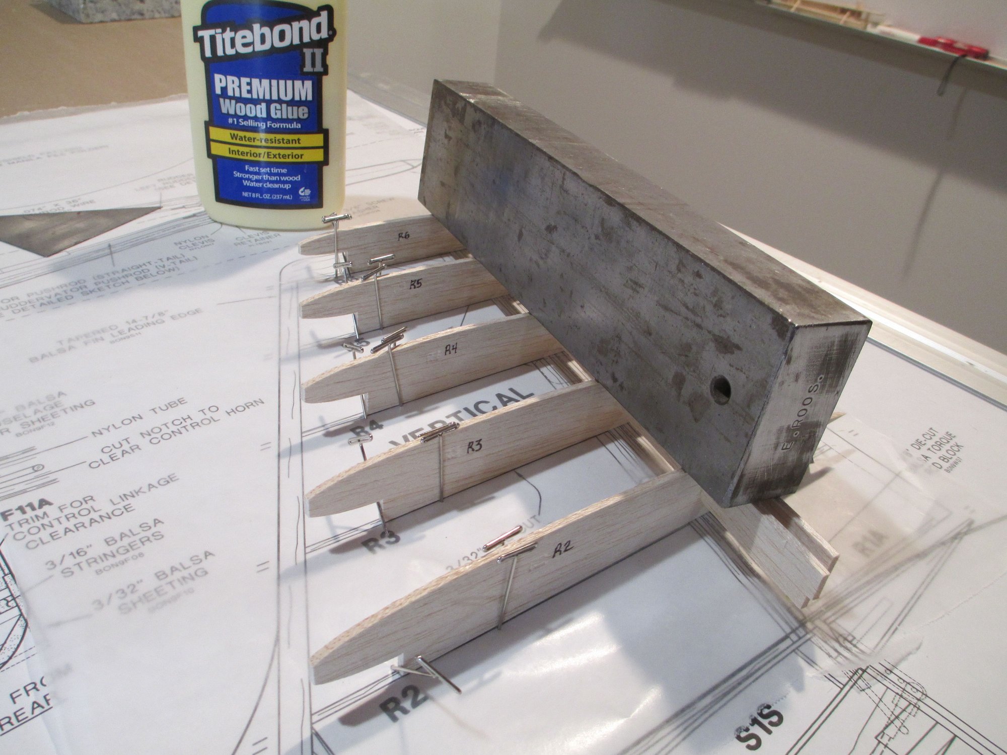
Spars were added and glued into position. I added a block of weight over the top to ensure each rib was flush against the build table.
Last edited by VincentJ; 07-06-2019 at 10:23 AM.
07-06-2019, 01:30 PM
#67
Thread Starter
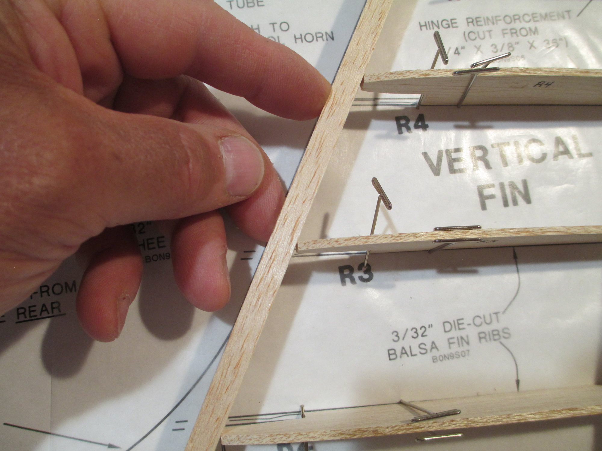
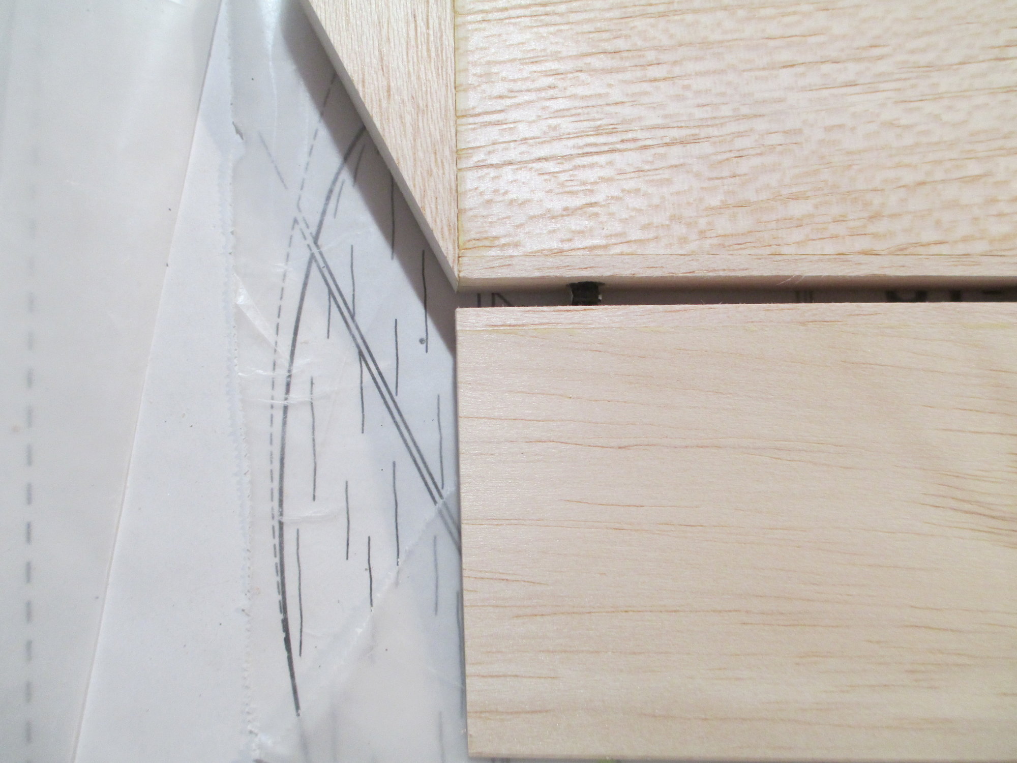
The fin's leading edge need some attention before glue-up. I don't like the contact area between the front of each rib and the back of the leading edge.
This is how I will fix the problem. I'm once again using my aluminum angle stock with sandpaper attached on one side.
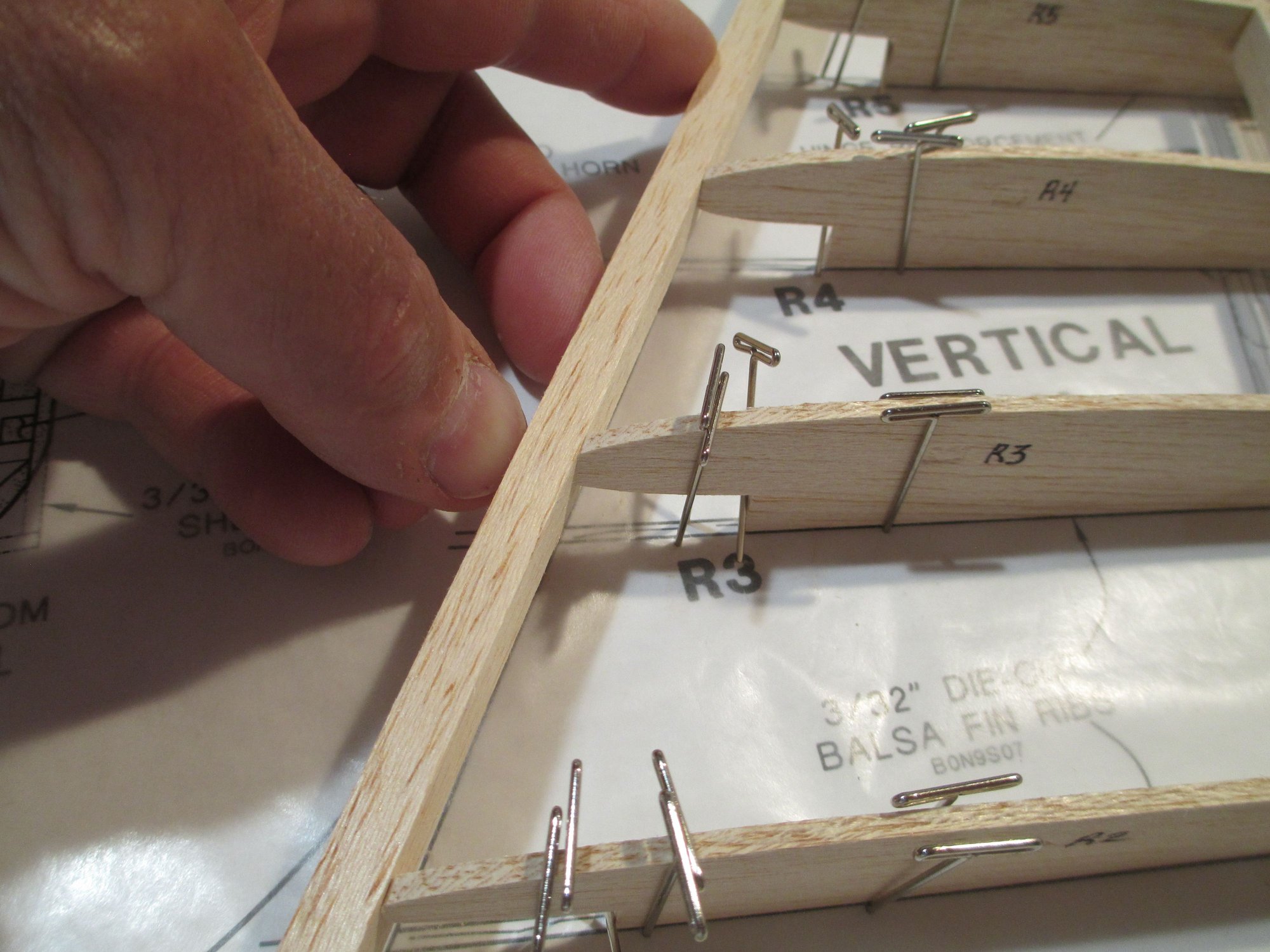
After a few passes the contact between rib and LE stock is perfect.

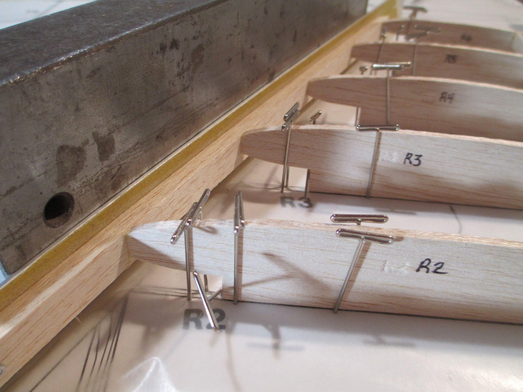
With the glue now applied, I'll let it dry before moving onto the next step...
Last edited by VincentJ; 07-06-2019 at 04:26 PM.
07-06-2019, 04:27 PM
#69
Thread Starter
07-07-2019, 06:29 AM
#70
My Feedback: (2)
You are quite welcome, Vincent, It is so cool to see something built with such attention to detail. Its time for me to start building and become a much better builder and detailer!
I am going flying this morning and hopefully the wind isn't as strong as it was the other day
Take Care
Michael
I am going flying this morning and hopefully the wind isn't as strong as it was the other day
Take Care
Michael
07-07-2019, 02:58 PM
#72
Thread Starter

One side of the Rudder/Fin has been planked.
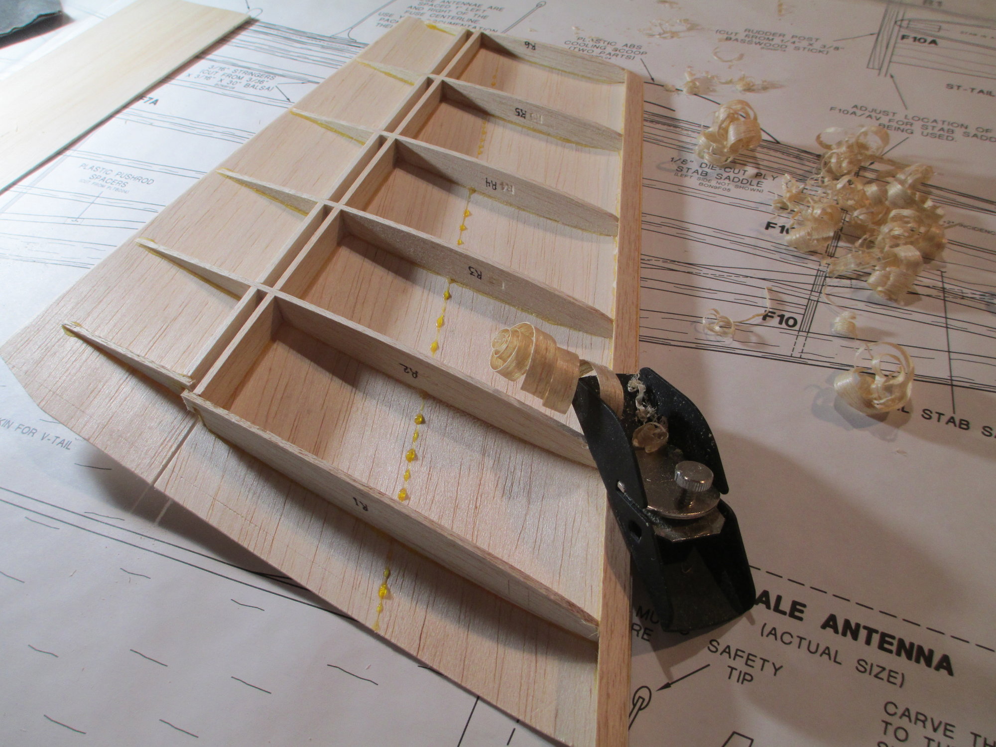
The cradle tabs were removed and before the sheeting begins, the leading edge must be shaped flush to the tops of the ribs. I find it extremely satisfying watching a good curl come out of my hand plane.


Similar to the elevator halves, the rudder also has four 1/8" torque rod blocks which have been sized and epoxied in place.
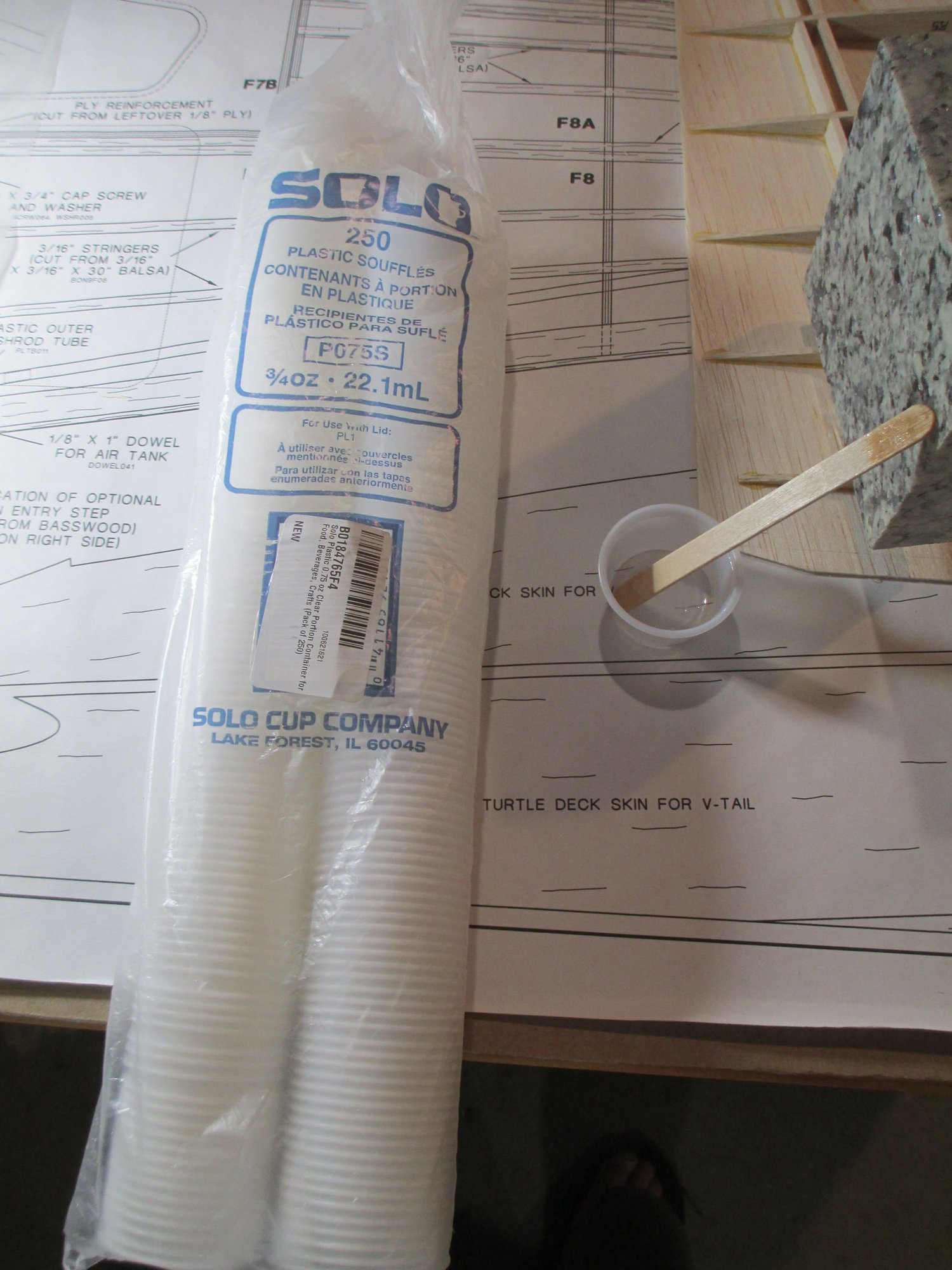
If you're like me you have been buying your mixing cups from your local hobby shop. Tired of overpaying for them, I decided to go on Amazon and purchase these 3/4 oz. mixing cups for about 7 bucks! They don't however have the measurement lines on the side.
07-08-2019, 05:34 AM
#73

RIP little girl!
Beautiful job as always Vince. I just had the worse holiday weekend of my life. My new best buddy passed. We didn't know she had been exposed to Parvo before she was old enough to vaccinate. I ran up a credit card trying to save her but she could beat it. RIP Sandy.
