


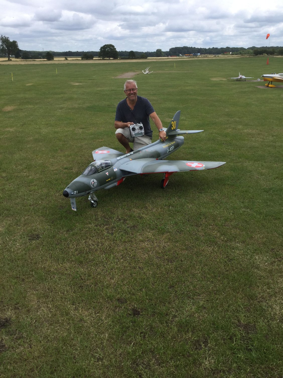
Introducing the TopRC Model Hawker Hunter - New Scale Jet
 04-24-2019, 08:39 AM
#76

Thanks Gary.
3s would probably do it. The JP unit takes up to 6s. Please provide the info on yours.
3s would probably do it. The JP unit takes up to 6s. Please provide the info on yours.


 12-23-2019, 01:01 PM
#79

Hi.
I am in the final stages of my build and have a question.
I know the wing tubes are clamped to the fuselage, but what prevents the wing from sliding off the tubes since nothing hold the wing to the fuslege? Only way I see is to glue the tubes to the wings, screw the wing to the fuselage at the root, or insert a screw in the bottom of the wing that goes through the wingtube.
How have you guys done it?
Thanks in advance for your answer.
Regards
Eduardo
12-23-2019, 01:05 PM
#80

Hi.
I am in the final stages of my build and have a question.
I know the wing tubes are clamped to the fuselage, but what prevents the wing from sliding off the tubes since nothing hold the wing to the fuslege? Only way I see is to glue the tubes to the wings, screw the wing to the fuselage at the root, or insert a screw in the bottom of the wing that goes through the wingtube.
How have you guys done it?
Thanks in advance for your answer.
Regards
Eduardo
I am in the final stages of my build and have a question.
I know the wing tubes are clamped to the fuselage, but what prevents the wing from sliding off the tubes since nothing hold the wing to the fuslege? Only way I see is to glue the tubes to the wings, screw the wing to the fuselage at the root, or insert a screw in the bottom of the wing that goes through the wingtube.
How have you guys done it?
Thanks in advance for your answer.
Regards
Eduardo
12-23-2019, 01:20 PM
#81
Hi.
I am in the final stages of my build and have a question.
I know the wing tubes are clamped to the fuselage, but what prevents the wing from sliding off the tubes since nothing hold the wing to the fuslege? Only way I see is to glue the tubes to the wings, screw the wing to the fuselage at the root, or insert a screw in the bottom of the wing that goes through the wingtube.
How have you guys done it?
Thanks in advance for your answer.
Regards
Eduardo
I am in the final stages of my build and have a question.
I know the wing tubes are clamped to the fuselage, but what prevents the wing from sliding off the tubes since nothing hold the wing to the fuslege? Only way I see is to glue the tubes to the wings, screw the wing to the fuselage at the root, or insert a screw in the bottom of the wing that goes through the wingtube.
How have you guys done it?
Thanks in advance for your answer.
Regards
Eduardo
02-07-2020, 06:23 AM
#82

I have just taken delivery of my Top RC Hunter the main gear doors are missing from the fuselage and there is no instruction manual with a check list of what should be provided, I see in this thread you all appear to have the small inner doors hinged from the fuselage, I'm trying to find out if they are missing from my delivery.
Regards
Paul
Regards
Paul
06-22-2020, 06:31 AM
#84

I downloaded the manual. The front cover says the CG is 290mm from the leading edge at the wing root. Yet inside the manual, it says 240mm from the same place. That's a 50mm difference, almost 2 inches. I read thru this thread and didn't find anyone dealing with this issue. Can you guys who have flow this jet tell us your CG location? Thanks!
06-22-2020, 06:33 AM
#85
I downloaded the manual. The front cover says the CG is 290mm from the leading edge at the wing root. Yet inside the manual, it says 240mm from the same place. That's a 50mm difference, almost 2 inches. I read thru this thread and didn't find anyone dealing with this issue. Can you guys who have flow this jet tell us your CG location? Thanks!
06-22-2020, 12:39 PM
#87
Be careful, there is a huge balance shift on this model. I test flew one Saturday for a friend, it was hugely nose heavy because it was balanced with landing fuel only. I suggest balancing with half a tank.
Dave.
Dave.
06-22-2020, 12:44 PM
#88
Balance EMPTY (full air trap) at 290mm and it will be a good place to start.
P.S. Have never flown without the tanks.
P.S. Have never flown without the tanks.
Last edited by causeitflies; 06-22-2020 at 12:49 PM.
06-22-2020, 09:18 PM
#90
Yes, it was very nose heavy on take off. Will find out which balance point he used. I had him take a huge lump of lead from the nose after the test flight and I think maybe more will come out.
I had him take the tanks off just before we flew as the factory mounting points were not parallel to each other or fuselage! He’s adjusted them now and we will try again this weekend.
Also the wing panels worked out on one side taxiing on our grass strip. The soft alloy tubes need a block inside I think.
Dave
06-23-2020, 03:33 AM
#91
Yes, it was very nose heavy on take off. Will find out which balance point he used. I had him take a huge lump of lead from the nose after the test flight and I think maybe more will come out.
I had him take the tanks off just before we flew as the factory mounting points were not parallel to each other or fuselage! He�s adjusted them now and we will try again this weekend.
Also the wing panels worked out on one side taxiing on our grass strip. The soft alloy tubes need a block inside I think.
Dave
06-23-2020, 04:55 AM
#92
You Brits are usually more articulate than we in the colonies, so I'm having trouble visualizing the meaning of the bold. Like, where did the jet get fuel if you took the tanks off before you flew? And, are the soft alloy tubes the SPARS? If so, and they're soft, I'd say taxiing is the least of the worries. Maybe a little edification would help. Thanks!
I believe Dave is refering to the wing tanks. With respect to the aluminum tubes, the two thicker ones are supposed to be glued to the wing, and when attached to the fuselage they are clamped by a clamp installed in the factory. For this a hole must be drilled in the bottom of the fuselage to access the screw to tighten the clamp.
Regards
Eduardo
06-24-2020, 04:05 AM
#93
Hi,
I believe Dave is refering to the wing tanks. With respect to the aluminum tubes, the two thicker ones are supposed to be glued to the wing, and when attached to the fuselage they are clamped by a clamp installed in the factory. For this a hole must be drilled in the bottom of the fuselage to access the screw to tighten the clamp.
Regards
Eduardo

 07-12-2020, 03:22 AM
#95
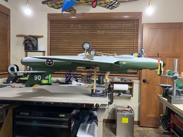
I finally got going building my actual top RC Hawker Hunter. The first thing I noticed that needed changing was the flap hinges. I didn�t like the way they stuck down from the lower wing surface so I did this modification to make them flush. So far they seem strong and work fine and they look much more Scale. Also there are fewer protrusions to get caught and broken during handling.


10-15-2020, 07:28 AM
#96
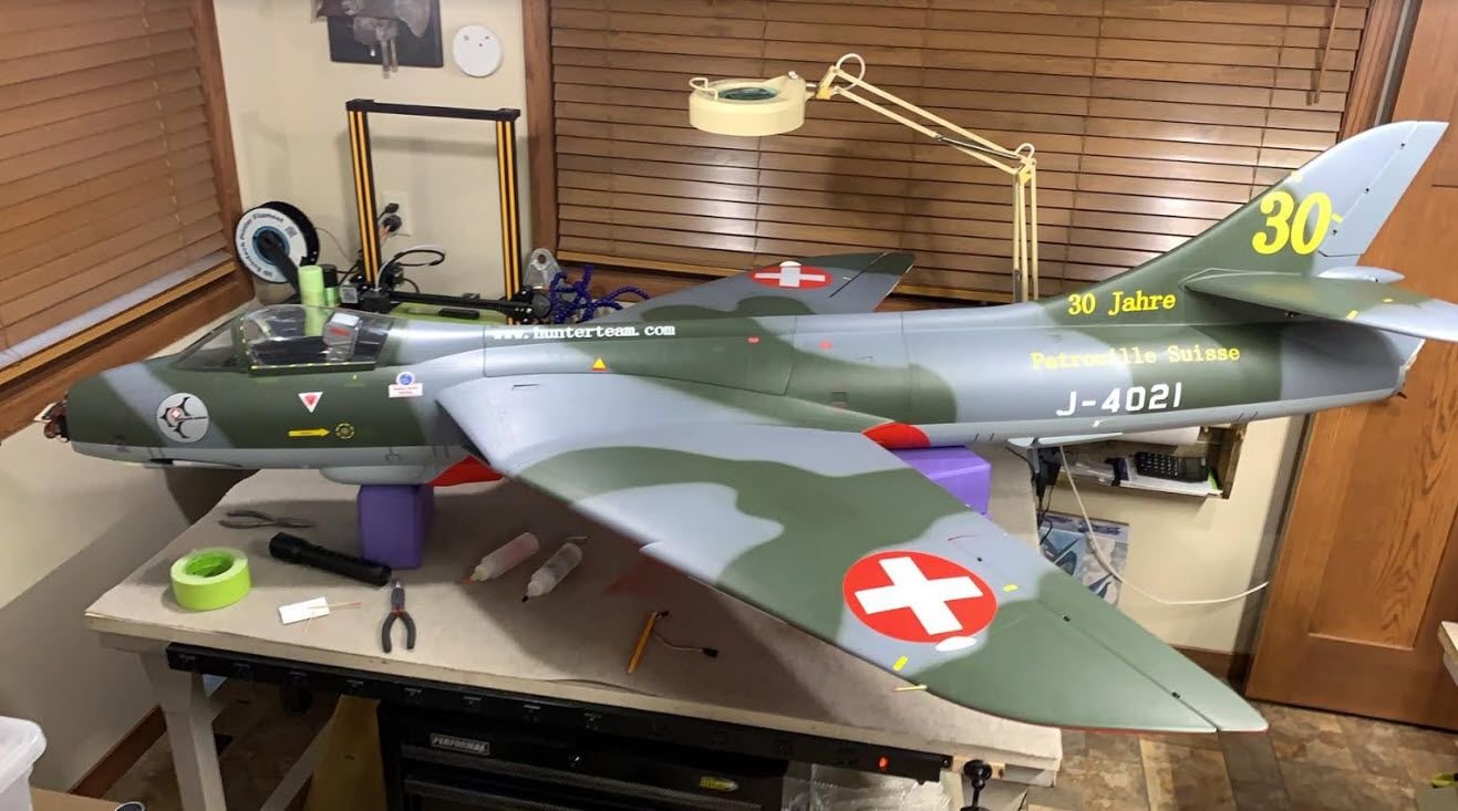
I hate to keep beating a dead horse, but I'm now balancing my TopRC Hawker Hunter and I want to address the CG location again. In my original post, I noted the manual says 2 different measurements "from the same location". Well, I was wrong, it gives 2 different numbers from TWO different locations. The inside of the manual gives 240mm from the outer tip of the air inlet. The cover of the manual states 290mm from the tip of the wing root joint. Note in my scaled photo that there is close to a 1 inch difference in those two reference locations. So where is your reference location for the 290-300mm measurement? Thanks for the help!

The .98" is the difference between the two CG starting points. I didn't show the 240mm because almost everyone agrees that is not the right number.
The .98" is the difference between the two CG starting points. I didn't show the 240mm because almost everyone agrees that is not the right number.
 10-15-2020, 09:27 AM
#98
Hi, f
From what I've researched in several sources online, the perfect CG for this plane from people that have flown it, is located right at the dot (.) after the "www" that is incribed in the turbine mounting plate. There is where I have my CG and I pretend to maiden it this weekend.
Regards
Eduardo

From what I've researched in several sources online, the perfect CG for this plane from people that have flown it, is located right at the dot (.) after the "www" that is incribed in the turbine mounting plate. There is where I have my CG and I pretend to maiden it this weekend.
Regards
Eduardo
10-15-2020, 11:27 AM
#99
Hi, f
From what I've researched in several sources online, the perfect CG for this plane from people that have flown it, is located right at the dot (.) after the "www" that is incribed in the turbine mounting plate. There is where I have my CG and I pretend to maiden it this weekend.
Regards
Eduardo
From what I've researched in several sources online, the perfect CG for this plane from people that have flown it, is located right at the dot (.) after the "www" that is incribed in the turbine mounting plate. There is where I have my CG and I pretend to maiden it this weekend.
Regards
Eduardo
Last edited by Pull Up Now!; 10-15-2020 at 11:33 AM. Reason: add text
