


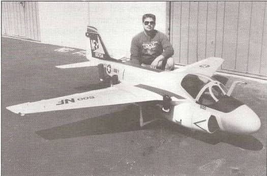
a6 intruder from the movie "flight of the intruder"


 01-19-2021, 08:21 PM
#102

Actually, there was at least three drop modes but I don't know exactly what they were called or how they were dropped, manually or automatically. Guess that's what I get for being a Prowler tech ")
01-20-2021, 02:15 AM
#103

Considering there is only one fast low pass per flight round I will opt for shedding all the weight at one time  These will be molded of endothermic resin to make them light weight but the nose/fuse end gets proper weight to see it remains where is should be after release...not flipping end over end like non-retarded iron.
.........
These will be molded of endothermic resin to make them light weight but the nose/fuse end gets proper weight to see it remains where is should be after release...not flipping end over end like non-retarded iron..........
Last edited by Flite-Metal; 01-20-2021 at 06:14 PM.
01-20-2021, 08:30 AM
#104
Tomorrow I will take a few pics of some of the vacuum formed parts created for the movie 6's. They will become molds to pour new plugs for vacuum formed parts to accompany the new parts we are printing,
Last edited by Flite-Metal; 01-20-2021 at 05:40 PM.
01-20-2021, 05:08 PM
#105


Big A-6 Intruder kit - mfg help please
I think everyone would be interested in seeing what you are actually going to produce and if they will be 3D printed or old school vacuum formed.
01-20-2021, 05:34 PM
#106
Just curious - why don't you post pics of the parts YOU are actually going to make instead of recycling my pic of the original DCU parts I have from my 4 year old post...Big A-6 Intruder kit - mfg help please I think everyone would be interested in seeing what you are actually going to produce and if they will be 3D printed or old school vacuum formed.
..........
.....
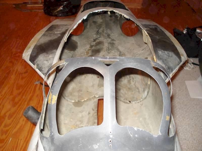
..We are creating new plugs for vacuum forming by pouring high temp resin within the original molded parts. The canopy parts are in West Va. to create new plugs. Being concave I thought it best to utilize the talent of a more experienced scratch builder who does this type thing regularly.
Tomorrow I will take pics of my own parts, sans canopy parts, and post them... I have deleted the pic you posted earlier. None of these parts are being printed. Since they are in essence "molds" they provide an excellent opportunity to save time and money.
As I have shown, there are several details I am printing then creating molds for pouring endothermic resin. The Mk-82's, spoileron track, AEW parts, landing gear sheaths, and cockpit details as an example.
Last edited by Flite-Metal; 01-21-2021 at 06:49 AM.
01-21-2021, 06:38 AM
#107
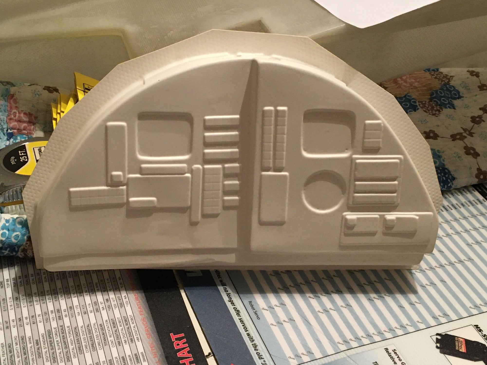
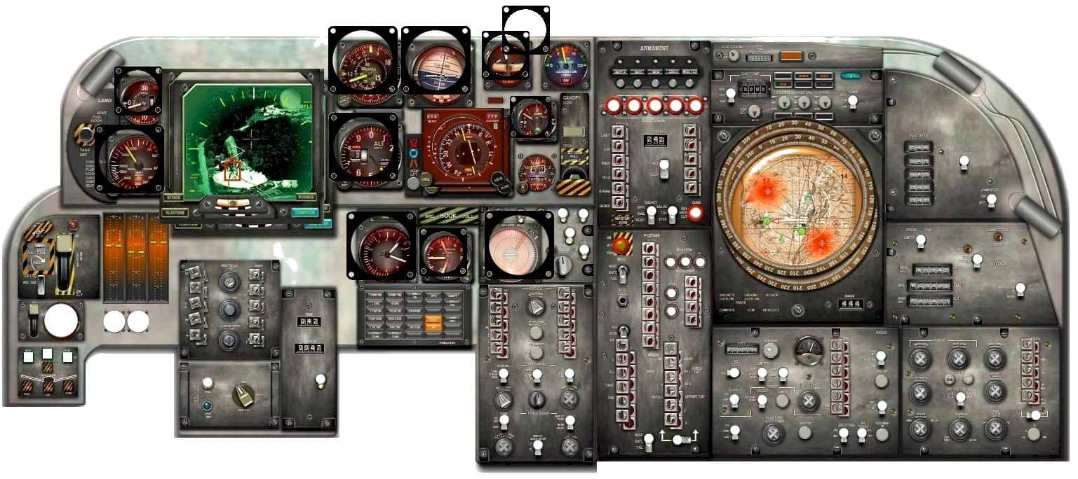
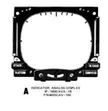
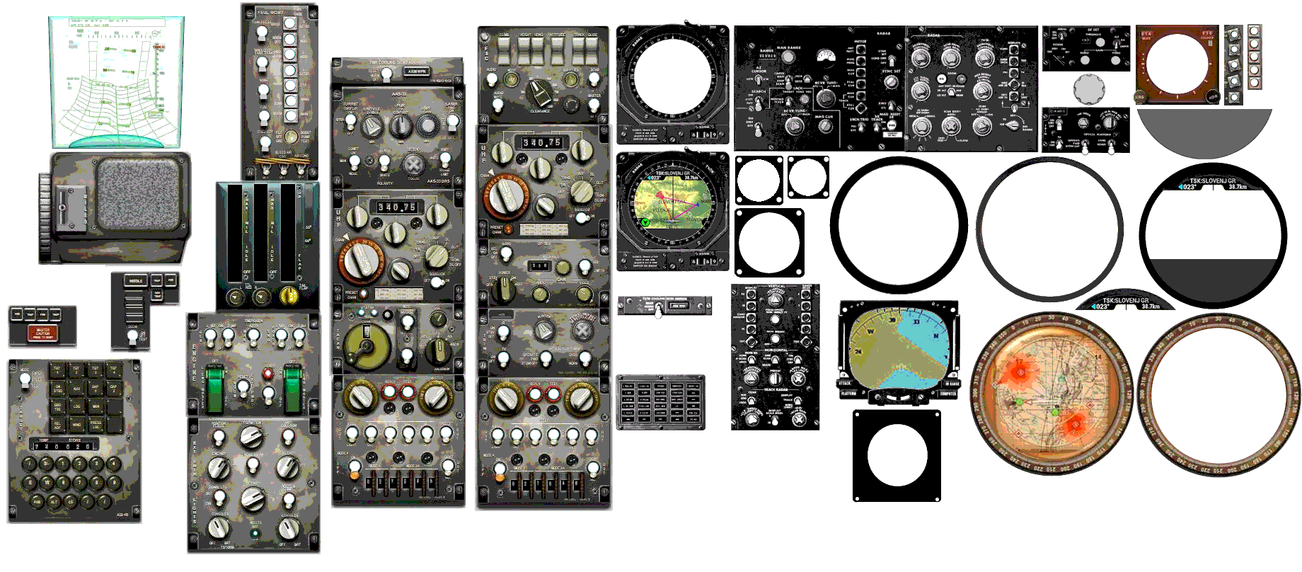
The 6's produced by DCU were "supposed to be" 6A's. Above is the kinda-sorta 6A panel Mark created. I am bringing this to an E standard with a B/N right hand side interchangeable to be a virtual KA6D panel.
...
.. ..
..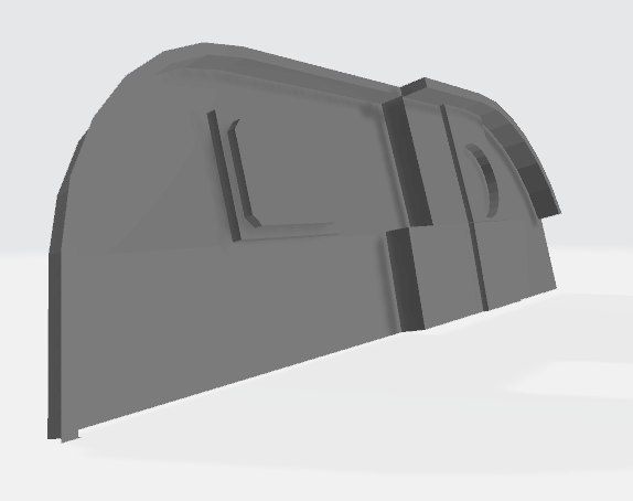
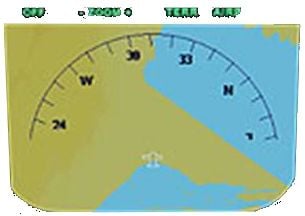
.....The original DCU instrument panel shape is obviously a far cry from the proper shape, much less the instrument layout. The image below illustrates our instrument panel (color) showing the individual components slightly offset from their positions.
..
Last edited by Flite-Metal; 01-22-2021 at 01:51 AM.
01-21-2021, 05:33 PM
#109
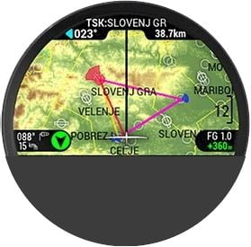
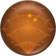
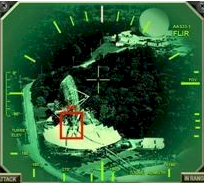
Our instrument panel is builder assembled of 3D compounded layers. For example: Panel base (medium grey). Individual panel sections (black & color), Instrument bezels (black-orange-red), radar and FLIR screens (transparent/w/color), toggle switches (aluminum/black/red) radar bezels (grey/gold/black/aluminum), dials (grey/charcoal), push-push illuminated buttons, LED panel lighting.

Last edited by Flite-Metal; 01-22-2021 at 01:52 AM.
01-21-2021, 05:41 PM
#110
Sorry if you took my post the wrong way, but I wasn't offended at all. I was just curious as to why you were posting an original part pic instead of new images of the awesome work you're doing. Now explained on how you're using the original parts as moulds, it makes sense.
01-22-2021, 02:29 AM
#111
In order to vacuum form, individual forms/plugs are required for each shape to be formed. For most parts the originals are whole and undamaged. For those unaware the female side of a vacuum formed part has more detail than the protruding convex side. Low viscosity high temp resin can be poured into the concave shape to form new convex masters/plugs.
High temp resin must be used because of high temperature of the vacuum former. This works for many of these parts though the instrument panel is a much more detailed surface than the majority of parts. We are utilizing as much CNC based processes as possible to expedite the many time consuming tasks.
High temp resin must be used because of high temperature of the vacuum former. This works for many of these parts though the instrument panel is a much more detailed surface than the majority of parts. We are utilizing as much CNC based processes as possible to expedite the many time consuming tasks.
Last edited by Flite-Metal; 01-22-2021 at 02:32 AM.
01-22-2021, 03:37 AM
#112

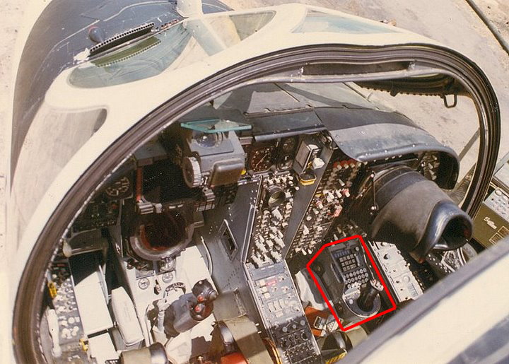
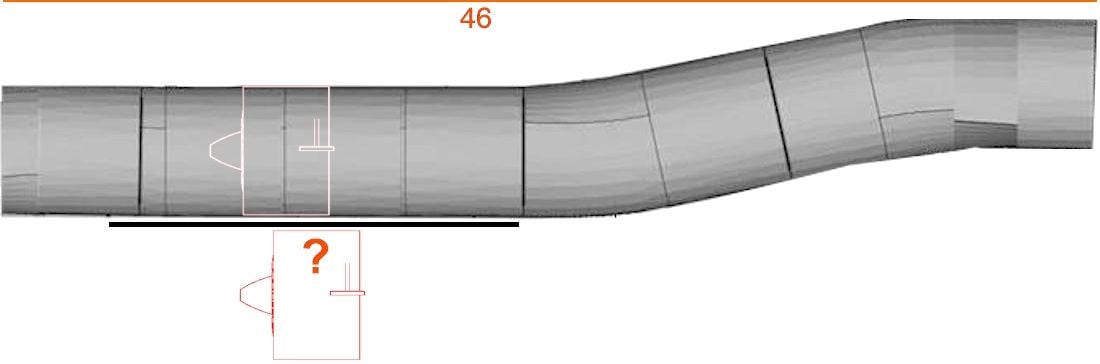
Flight-Metal, I'm going to throw another variant at you on the Prowler. At the 2:30 mark on the video, Prowler 503 is shown headed to a catapult. If you look closely at the centerline hardpoint, you will see the weapon pod is different. I don't remember the exact size and shape but I do know it's very different from the ones mounted on the wings. That particular unit was almost never carried on a wing station as it was draggier than the standard shaped one. Something you can't see is that, on the left side below the two finned areas on the sides of the pod, roughly half way down are square access hatches that are held on by four camlocks. The hatches are roughly 6" square and are shaped to blend into the surface. Can't tell you any more about that unit because it's still classified 
https://www.youtube.com/watch?v=Jy04eBLAUrw
https://www.youtube.com/watch?v=Jy04eBLAUrw
Last edited by franklin_m; 01-22-2021 at 03:40 AM.
01-22-2021, 05:03 AM
#113
Thanks...however, from a practical sense...since this is a model not a museum replica...the ECM pod I have is what is on the EA6A and if we are fortunate to eventually do a B.
.. ..
..
..Last edited by Flite-Metal; 01-22-2021 at 05:06 AM.
01-22-2021, 05:44 AM
#115
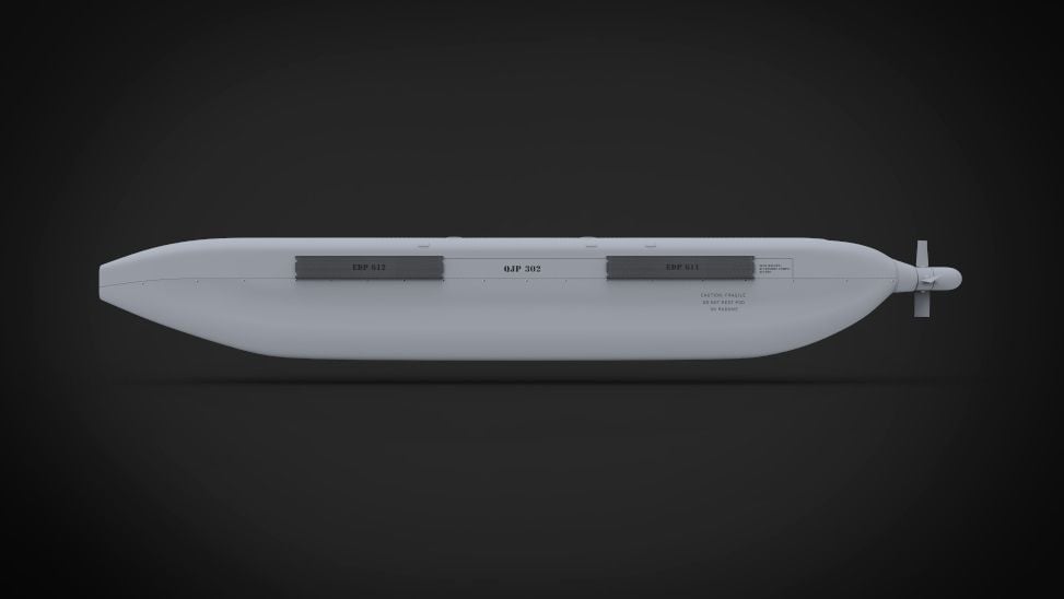
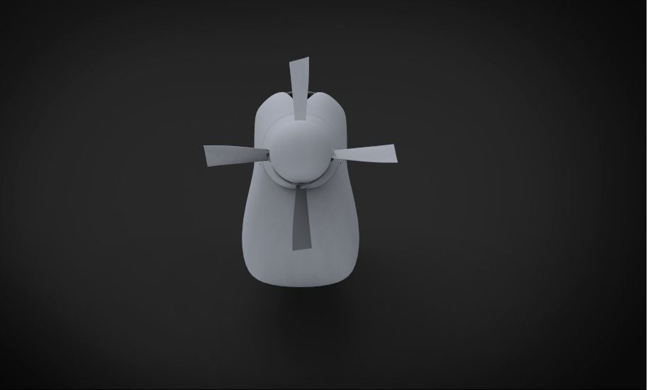
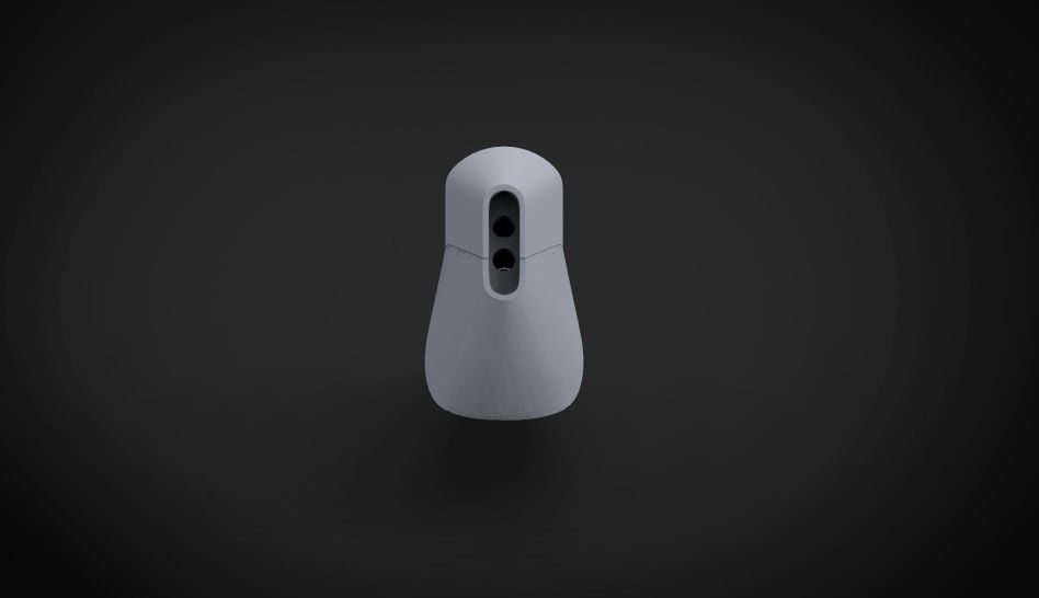
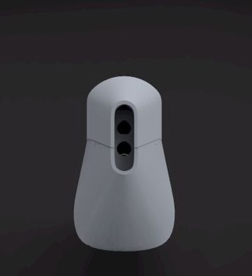
FlightMetal, one thing that isn't classified is, with the CG renderings of the pods, there is an error on the rear view. The opening at the rear is totally open, no baffles or anything inside blocking it. Two other things on the renderings:
- the dark rectangles on the side view are actually raised horizontal fins that are roughly .5" high and roughly gapped about the same as the fin width, I'm thinking probably .125" though I could be wrong.
- The upper part of the pods had a identification number right behind the aft set of fins on the side, just above the panel line. If you look closely at the 20 second mark of the last video with the Prowler from VAQ-134, you can see it in a slightly darker grey than the rest of the pod. In fact, when the wings unfold, it becomes more visible in the wing's shadow. IIRC, in the days where the planes were still painted gull grey and white, the number on the pod was painted in black on both sides.
- The pods used on the EA-6A and the EA-6B were the same, other than the one on the centerline having a different shape to the bottom. The only things that changed were what was inside and that is what's still classified to this day. I don't know how things were when Franklin was in the Prowler community but, in my day, we weren't even allowed to take a picture of a loaded plane unless the pod was completely assembled. Even if there weren't pods loaded, other areas still had to be closed up or we risked getting our cameras taken and the film destroyed
- Also visible in the video I referred to is a spacer fairing between the wing hard point and the top of the pod. Unlike MERs and TERs, the pod had to be aligned with the aircrafts flight path so the front of the pods needed to be lower than if they were just mounted to the wing racks. The spacers weren't needed on the centerline as it was already aligned with the plane. Can't say anything else on them without breaking the law
Last edited by Hydro Junkie; 01-22-2021 at 05:55 AM.
01-22-2021, 08:46 AM
#116
Copy. Just trying to help you out. That's an ALQ-99 pod configured for a certain part of the frequency range that you've modelled. Ironically, while that one likely would have been carried on wing stations on an EA6A during times when those were in use, it's the one mentioned by Hyro and me that likely would have been on the centerline in combat - due to principal threat systems they faced during '72-'73 in Vietnam (only tactical employment of EA6A).
01-22-2021, 08:49 AM
#117
Everything you said is correct. And it's still a security breach to photograph a pod w/o the radome on it ... antennas a classified. Of course other technical details are as well of course. But in terms of what likely would have been on the centerline of an EA6A in combat in '72-'73, it would have been the one you mentioned in the video ... with the fat radome. Heck, I was still carrying one on the centerline of my EA6B thirty years ago around this time.
Last edited by franklin_m; 01-22-2021 at 10:08 AM.
01-22-2021, 09:17 AM
#118
Interesting differences in the CAD and your description of the ECM pods. Don't recall the point of origin for the CAD. I have had it a couple of years. Its amazing the number of aviation CAD files out there. I believe this and the retarded Mk-82 came from the same source. I do not have a photo of the rear end. The illustrated bulkhead would obviously have to exist but the drawing is probably an assumption considering it was exhausting a tremendous amount of heat.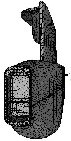
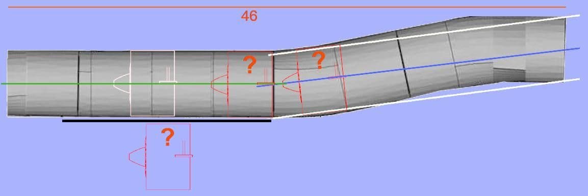
.................This is another CAD drawing of the pod...I turned it so you can see this one does not have lightening holes in the bulkhead. I am curious if the outboard section of the pod attachment to the pylon is correct in this drawing. Also, as you stated, this "outboard" pod is set at an angle to the pylon. That gives me greater confidence the drawing is of the actual pod and not being dreamed up by its author. This matches the engineered line drawing I have of the B and EA-6A
.................
Last edited by Flite-Metal; 01-22-2021 at 09:37 AM.
01-22-2021, 03:05 PM
#119
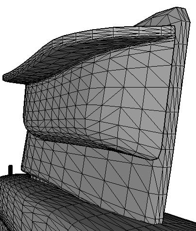
Okay, the CAD drawings show a fairly good rendering of station 1, the outboard left hardpoint. The bottom of the hardpoint is incorrect where it meets the top of the pod, something that can be confirmed looking at pictures. The CAD drawing that shows the rear of the pod is also wrong. The CG rendering is much closer, once you remove the baffle from the inside.
01-23-2021, 03:15 AM
#120
The pod and the hardpoint are two separate parts. I will simply edit the internal rear to be a recessed flat w/o the two vent holes
................................................
................................................
 02-19-2021, 03:02 PM
#125

They need to go where you can make cg. Which usually means in a more forward position. But not always. That's what drives the location the most. Here is a good article from Schubeler https://www.schuebeler-jets.de/de/ed...ng-der-kanaele
Last edited by MarkF; 02-19-2021 at 03:15 PM.