


a6 intruder from the movie "flight of the intruder"
 02-19-2021, 03:19 PM
#126

You will get your best answers on rc groups in the large jet forum if you start a new thread. But I will give you my 2c. Build the model first with all gear and paint. Well maybe you can skip the paint but build the model with servos and retracts. Then place all your equipment in the model until you reach your ideal cg. That means fans, batteries and esc. You will need to move them around until you make cg. Putting your fan in an ideal spot does no good if you have to add a lb of lead in the nose.
Last edited by MarkF; 02-19-2021 at 03:39 PM.
 02-19-2021, 04:00 PM
#127

They need to go where you can make cg. That's what drives the location the most. Here is a good article from Schubeler
https://www.schuebeler-jets.de/de/ed...ng-der-kanaele
https://www.schuebeler-jets.de/de/ed...ng-der-kanaele
Thanks for the heads up.
CG has absolutely nothing to do with equipment/fan placement. CG is the aerodynamic distribution of the AUW with respect to wing and horiz
stab area, shape, and moment. Perfect CG results in a neutral balance point. Depending on plane form...perfect CG is typically too sensitive. Some % of greater nose mass results in a more desirable flight behavior than a CG with with "0" differential distribution.
.................................................. ...........
With respect to the Grumman A6 Intruder family the CG is most radically effected by retraction of the landing gear due to its unusually long/tall strut and forward retraction. The CG remains constant while a desirable flight behavior must be "dialed in" during flight with the absence of complicated formulas and a huge dose of physics.
With respect to this model the CG of the original "Flight Of The Intruder" 6's was the blade spar attachment of the wing. No wing tube was used. Our design utilizes an aluminum wing tube with a phenolic tube sleeve. Weight distribution is not an issue space wise. Do not anticipate any nose weight to be required...considering the pair at 24s.
Last edited by Flite-Metal; 02-19-2021 at 04:31 PM.

The following users liked this post:
yeahbaby (02-19-2021)
02-19-2021, 05:05 PM
#131
02-21-2021, 07:55 AM
#132

To get a cleaner flow of air to the ducted fan face, fwd placement would be better than aft. Having said that, don't do it if it throws your CG off significantly, as MarkF was alluding to. Getting nice flow to the fan face is a bit more critical to ducted fan installations (and axial flow turbines), than to centrifugal flow turbines. 
02-21-2021, 08:17 AM
#133
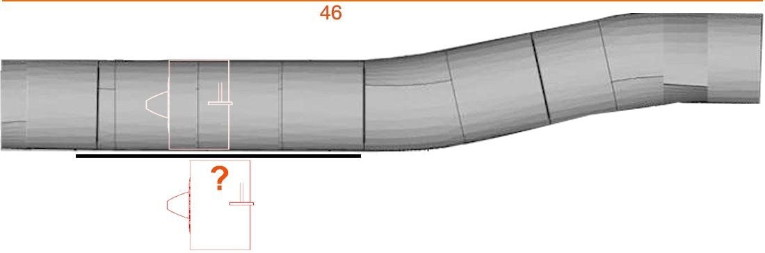
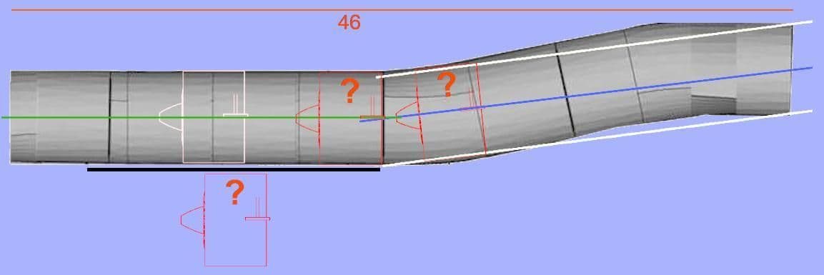
For multiple reasons I have decided to place the EDF at the rear end of the tube. Placing forward would impose severe CG issues. This also permits bottom EDF or turbine access.
This was the original EDF location.
This was the original EDF location.
Last edited by Flite-Metal; 02-22-2021 at 03:16 AM.
02-21-2021, 09:11 AM
#134

Ed,
Just looking at the overall configuration of the A-6 with the short nose and long tail arm, it looks like it would be very easy to end up with a tail-heavy model.
I'd seriously re-consider your aft placement of the fans, and move them as far forward as possible.
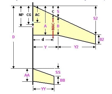
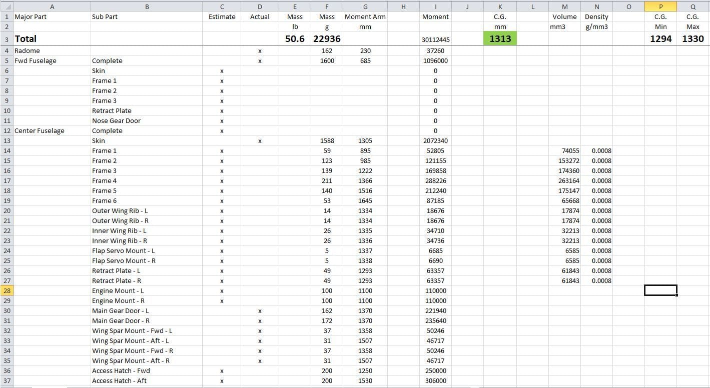
Use the c.g. calculator you posted above to determine the required c.g - aim for a 5% static margin, and then start a weight & balance spreadsheet with all the airframe parts and equipment to determine an optimum layout.
Use weight & c.g. estimates for each part of the airframe and equipment initially until you make real flight hardware, and then continuously update the spreadsheet with real numbers.
I did that with my Buccaneer and it was extremely helpful - I only ended up with a small amount of nose ballast, which I think I could have significantly reduced or eliminated with additional flying.
Paul
Just looking at the overall configuration of the A-6 with the short nose and long tail arm, it looks like it would be very easy to end up with a tail-heavy model.
I'd seriously re-consider your aft placement of the fans, and move them as far forward as possible.
Use the c.g. calculator you posted above to determine the required c.g - aim for a 5% static margin, and then start a weight & balance spreadsheet with all the airframe parts and equipment to determine an optimum layout.
Use weight & c.g. estimates for each part of the airframe and equipment initially until you make real flight hardware, and then continuously update the spreadsheet with real numbers.
I did that with my Buccaneer and it was extremely helpful - I only ended up with a small amount of nose ballast, which I think I could have significantly reduced or eliminated with additional flying.
Paul
02-21-2021, 08:17 PM
#135

Ed,
Your design will only accommodate the Jetfan 110? How about other power plants such as the Dynamax ducted fan unit (127mm)? I'm not sure what the Jetfan weights completely assembled, but the Dynamax units I have are about 2 1/2 lbs each (Fan unit, Motor, ESC and power leads).
Your design will only accommodate the Jetfan 110? How about other power plants such as the Dynamax ducted fan unit (127mm)? I'm not sure what the Jetfan weights completely assembled, but the Dynamax units I have are about 2 1/2 lbs each (Fan unit, Motor, ESC and power leads).
02-22-2021, 02:53 AM
#137
Ed,
Your design will only accommodate the Jetfan 110? How about other power plants such as the Dynamax ducted fan unit (127mm)? I'm not sure what the Jetfan weights completely assembled, but the Dynamax units I have are about 2 1/2 lbs each (Fan unit, Motor, ESC and power leads).
Your design will only accommodate the Jetfan 110? How about other power plants such as the Dynamax ducted fan unit (127mm)? I'm not sure what the Jetfan weights completely assembled, but the Dynamax units I have are about 2 1/2 lbs each (Fan unit, Motor, ESC and power leads).
MAC6's will accommodate any size EDF or appropriate power turbine. The original 1:5.5 Intruders flew on ByroJet @ 6.25" diameter. Our Intruder's scale exhaust diameter is not pre-cut. The "scale exhaust diameter" can be cut up to 5 inches. It is not pre-cut. Weight of what is chosen for power is an element of CG management.
Last edited by Flite-Metal; 02-22-2021 at 03:08 AM.
03-14-2021, 10:05 AM
#138
